
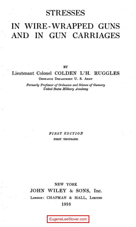
Stresses in Wire-Wrapped Guns and in Gun Carriages by Lieutenant Colonel Colden L’H. Ruggles, Ordnance Department, U.S. Army, formerly Professor of Ordnance and Science of Gunnery at the United States Military Academy, was written at West Point in 1910 and printed by the Military Academy Press for the use of cadets. It was not available to the public at all until the original edition ran out and John Wiley & Sons published this edition in 1916.
The book is the working companion to Lissak’s Ordnance and Gunnery — it cites Lissak by paragraph and page throughout and picks up exactly where the general text leaves off, on two problems Lissak treats only in outline: how a wire-wound gun is actually stressed, and how a gun carriage is actually loaded and sized.
Chapter I is the wire gun. A wire-wrapped gun is an inner steel tube, layers of wire wound onto it under tension, and a jacket and hoops over the wire; the jacket, not the wire, carries the longitudinal load, which is why the breech block screws into it. Ruggles works the design two ways — wire wrapped under constant tension, and wire wrapped under a varying tension calculated so that at the prescribed maximum powder pressure every layer of wire carries the same tangential stress — and takes both all the way through a worked section of a 12-inch gun’s powder chamber. The formulas come from General William Crozier’s Notes on the Construction of Ordnance Nos. 38 and 87, and behind those, Longridge.
Chapters II–IV are the gun carriage. Ruggles determines the forces the discharge brings on each principal part of the 3-inch field carriage, model of 1902 and of a 6-inch disappearing carriage, model of 1905 MI — taking each carriage apart into gun, cradle, rocker and everything below it — then computes the stresses in the individual parts of those two carriages and of the 5-inch barbette carriage, model of 1903, section by numbered section. The throttling-groove computations for the disappearing carriage are essentially the ones made for it in the Office of the Chief of Ordnance. Chapters V and VI finish with the mechanical engineering an ordnance officer needed in the same drawing room: toothed gearing for elevating and training gear, and the design of counter-recoil springs.
What Is in the Book
Every line in this table is a link. Click a chapter and the reader below jumps to it.
| Chapter | Subject | Pages |
|---|---|---|
| I | Elastic Strength of Wire-Wrapped Guns | 1–36 |
| II | Determination of the Forces Brought upon the Principal Parts of the 3-Inch Field Carriage by the Discharge of the Gun | 37–62 |
| III | Determination of the Forces Brought upon the Principal Parts of a Disappearing Gun Carriage by the Discharge of the Gun | 63–105 |
| IV | Stresses in Parts of Gun Carriages | 106–173 |
| V | Toothed Gearing | 174–227 |
| VI | Counter-Recoil Springs | 228–259 |
The scan is complete, title page through the last page of Chapter VI. The viewer runs to 270 leaves for a 259-page book — the extra eleven are the front matter, which the book numbers in roman. The table of contents below gives the printed book page for every entry.
Using the viewer: Use the Full Table of Contents button (bottom-right) to jump to any chapter or major section. Use the double caret (») symbol at top right of viewer to adjust scrolling. This is a large file — give it a moment to open.