
Chapter 29 of Naval Ordnance and Gunnery, Volume 2 — Fire Control covers the systems that control and guide a missile during flight. Consolidated here from the original scanned sub-pages into one illustrated, scrollable page, it covers the principal parts of a guided missile, the missile control systems (attitude control and path control), and the eight basic guidance systems — pre-set, terrestrial reference, inertial, celestial navigation, radio navigation, command, beam rider, and homing.
A. Introduction
29A1. General
The principal parts of a guided missile, aside from its airframe, are its propulsion system, its war head and fuze, and the systems that control and guide it during flight. Chapter 11 of this text includes a discussion of guided missiles in general, and goes into some detail about missile propulsion systems, war heads, and fuzes. The present chapter deals with missile control and guidance systems.
A guided missile is capable of controlling its flight path in accordance with information received from an outside source. Depending on the guidance system used, this information may be pre-set in the missile before launching, or it may be received in flight. Information received in flight is usually in the form of electromagnetic radiation: radio waves, radiant heat, or light. The missile may receive this information from the target, or from guidance devices near the launcher. A single missile may use a combination of two or more forms of guidance.
The control systems compare the present position and attitude of the missile with the flight path determined by the guidance system, and effect any necessary changes in missile trajectory.
B. Control Systems
29B1. Introduction
A guidance system is a robot device capable of directing the flight of a missile in response to intelligence set into it, or to commands originating from outside the missile. The functions of such a system are to stabilize the missile axes with respect to a desired flight path and to orient the missile with respect to a target. Figure 29B5 shows the three mutually perpendicular axes (yaw, pitch, and roll) which the guidance system must be capable of positioning correctly to accomplish the above functions.
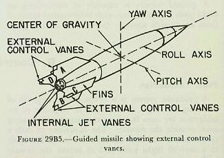
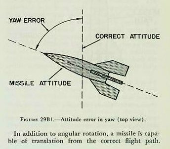
A missile in flight is subject to angular rotation about the yaw, pitch, and roll axes. Figures 29B1 and 29B2 show a missile with a yaw error and a pitch error respectively. If the missile is to remain stabilized with respect to the flight path, devices within the missile must be capable of detecting, measuring, and correcting yaw and pitch errors in order to keep the nose of the missile always pointed along the flight path. In addition, for the missile control vanes to function properly, the missile must not be permitted to roll about its longitudinal axis. Control of the angular motion of the missile about the yaw, pitch, and roll axes is called attitude control. Each guidance system must contain an attitude control system.

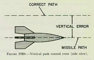
In addition to angular rotation, a missile is capable of translation from the correct flight path. Figures 29B3 and 29B4 show a missile with a lateral error and a vertical error respectively. In addition, a missile may develop a range error along the desired flight path. Control of the translation of the missile with respect to its flight path is called path control. Each guidance system must contain a path control system, the function of which is lateral control, vertical control, and range control.

29B2. Attitude control system
Control of the angular rotation of the missile about each of its three axes is accomplished by the attitude control system, all units of which are located within the missile. In addition, this system provides a reference common to both the missile and its control unit(s). It enables the missile to distinguish up from down and right from left, and to determine when it is rolling. For example, assume a missile is not roll-stabilized, and for some reason has rolled upside down. If a signal sent from the control unit ordered the missile to turn right, it would turn left, since it has no way of knowing that it is on its back.
In general, the following components are used to achieve attitude control in a guided missile: a reference, a detector, a controller, and control devices to turn the missile about its yaw, pitch, and roll axes.
Figure 29B6 shows how these components might be utilized in the pitch attitude control system of a missile. Similar components would be utilized in the same missile for the yaw and roll attitude control systems.

1. A reference is some device which will give the missile a known line in space from which to measure attitude errors. An example of a reference device is the gyroscope, whose attitude is fixed with respect to space. The orientation of the gyro spin axes with respect to the missile would depend upon the operational and design requirements of the missile. For example, in a surface-to-surface missile designed to maintain level flight with respect to the earth, the gyro spin axis would be set in the missile to coincide with the true vertical with respect to earth. Then any angular movement in yaw and pitch will be in a plane parallel to the earth’s surface and in a plane perpendicular to the earth’s surface respectively. If the gyro is to be employed for very long periods of time or while the missile is moving over an appreciable part of the earth’s surface, a primary reference such as the magnetic compass or average position of a pendulum must be used to keep the gyro spin axis precessed to the true vertical.
For an air-to-air missile designed to keep its nose pointed toward the target, it might be desirable to keep the gyro axis always perpendicular to the missile flight path. In this application, an additional device, such as a radar, would be required to determine the flight path and continuously keep the gyro spin axis precessed to the correct position.
If the gyro is to be employed as the reference device, one gyro can serve as a reference for any two of the three types of attitude control (yaw, pitch, and roll). Normally, two gyroscopes are used, one for the yaw and pitch control systems, and one for the roll control system.
2. A detector is a device that will measure any error that develops throughout the flight of the missile. If, for example, the gyroscope is used as a reference, a simple potentiometer can be used for the detector. If the potentiometer resistor is attached to the missile casing and the potentiometer wiper or arm is attached to a gyro gimbal shaft, any movement of the missile (and hence the resistor) will vary the position of the wiper on the resistor and cause the detector to measure a voltage proportional to the deviation of the missile from its correct attitude. This voltage, which will be very small, is used as the error signal.
3. A controller is a power device that is controlled by the small error signal. Since the signal detected is usually very small, it must be amplified before it can be used to drive servo motors to which are connected elements that cause motion of the missile about the various axes (yaw, pitch, roll). The controller usually consists of an amplifier and the necessary servo motors connected with it.
4. Various types of control devices positioned by the controller servo motor cause angular movement of the missile about the yaw, pitch, and roll axes.
a. External control vanes or movable fins mounted externally on the missile, and similar to the rudders or elevators on a conventional aircraft, can be moved in the stream of air passing over the body. They will cause a greater force of air pressure to be built up on one side of the vane or fin than on the other, causing the missile to shift angularly in any direction desired. For both yaw and pitch, control vanes within one plane can be moved simultaneously in the same direction. For example, in figure 29B5 we can achieve yaw control by moving vanes A and B in the same direction, and the missile will change course accordingly. To achieve pitch control, vanes C and D are moved simultaneously in the same direction. For roll control, it is necessary to develop a torque which will turn the missile about its longitudinal axis. To accomplish this, opposite control surfaces, such as A and B, are moved in opposite directions. The difference in pressure built up on opposite sides of these control vanes will tend to roll the missile about its longitudinal axis, thereby providing a method of roll control. These control vanes and fins, however, can operate only when the missile is traveling at velocities high enough to give an effective air flow past the vanes or fins. In addition, they will be of little use in missiles flying above the earth’s atmosphere where there is relatively little air.
b. Jet vanes placed in the stream of hot exhaust gases from the motor can be used to control the missile’s attitude until the missile attains sufficient velocity for the external control vanes or movable fins to become effective, or during the time the missile is above the earth’s atmosphere. The operation is similar to that of the external vanes and fins. Control is achieved by the proper positioning of the jet vanes in the high-velocity exhaust gases, just as the control vanes are moved in the air stream, in order to produce missile motion in the desired direction. Jet vanes, however, have a limited life due to the extreme temperatures they must withstand. The normal life of the jet vanes in the German V-2 rocket was approximately 60 seconds.
c. A gimballed motor is another device which may be used. The missile motor is mounted in a system of gimbals similar to the gimbal system used for a gyroscope. By causing the output of the controller servo motors to rotate the gimbals with respect to one another, the direction of the thrust of the motor can be changed, resulting in a change of heading of the missile. This device will operate at any missile velocity, and whether the missile is in or out of the atmosphere.
d. Auxiliary jets may also be used to change the direction of motion of a missile. They can be mounted around the periphery of the missile at its center of gravity to cause lateral or vertical displacement of the missile, or they can be mounted parallel to the main propulsion system so that the missile’s over-all line of thrust can be changed, thus creating a turning movement.
When the reference, detector, controller, and control devices are assembled and mounted in a missile, they provide the missile with the means for maintaining stable flight on the desired flight heading. Referring to figure 29B6, assume our missile on a given heading develops a pitch error. Movement of the missile in pitch causes rotation of the missile casing with respect to the gyro reference, thereby causing displacement of the detector resistor with respect to the detector arm or wiper. This movement, noted by the potentiometer detector, is measured as an error signal or voltage (proportional to the movement in pitch) and sent to the controller. Within the controller, the error signal is amplified and applied to the pitch servo motor. The pitch servo motor then moves the pitch control vanes to cause the missile to correct the pitch error. When the missile is once again at the correct attitude in pitch, the error signal has decreased to zero, and the control vanes have returned to their neutral position.
29B3. Path control system
The path control system normally acts through the attitude control system. It must provide the orders or navigational information to the attitude control system to cause the missile to take the flight path for which the missile was designed. As explained above, the path control system must operate to keep the missile on its designed flight path to the target by providing a means for lateral, vertical, and range control.
Path control can be achieved by making the missile believe it has an attitude error. For example, if the missile is displaced laterally from its path, it may be made to move to the proper path by making it think it has a yaw attitude error. Correcting this false error, the missile will change its heading until it reaches the proper position, at which time another false error is sent to the yaw control system to bring the missile back to its proper attitude. Vertical control can be accomplished in a similar manner by making the missile think it has an error in pitch. One method of controlling range is by utilizing an order from the path control system to cut off the fuel supply to the motor of the missile when the desired range is attained.
In order to provide the attitude control system with the proper orders or navigational information to enable the missile to keep on the desired flight path, each path control system must consist of the following components: tracker, computers, directing devices.
1. Tracker. Before any intelligent commands can be sent to the missile, it is necessary to know the location of the missile with respect to the target. If the missile is not on the desired path to the target, the tracker will observe an error. The tracker may be in the missile, on the ground, or in the air. Tracking is accomplished optically, by radar, or by some means which utilizes a distinguishing feature of the target or missile against its background. For long range all-weather tracking, radar has been found most satisfactory.
2. Computers. The computers calculate directing signals for the missile by use of information from the tracker. The directing signals will tell the missile how much to move the control surfaces to properly position itself on the desired flight path. Computing may be accomplished on the ground, in the missile, or in both places. A missile may use more than one computing element. For example, an altimeter may be used to maintain the missile at the correct altitude, and an air log computer may be used to initiate a signal to cut off the fuel to the propulsion system when a pre-set range has been recorded.
3. Directing devices. Directing is the process of sending the computed order to the missile. This can be accomplished by sending radio or radar signals to a receiver in the missile when directing is to be accomplished from the ground. When directing is to be accomplished within the missile, the computed order is sent from one sub-component to another by electric, pneumatic, or hydraulic signals.
The directing signal can now be introduced into the controllers of the attitude control system either to correct the missile’s lateral or vertical deviation from the desired flight path or to cause the missile to change course or altitude. In addition, the directing signal can be used to vary the propulsive force of the missile and hence the range.
C. Basic Guidance Systems
29C1. General
As has been previously stated, every guidance system consists of an attitude control system and some sort of a path control system. The name of the path control system depends upon the unique manner in which path control is accomplished. Since nearly all missiles use the same type of attitude control system, it is common practice to refer to the guidance system by the name of the path control system. The following is a list of the eight basic guidance systems:
- Pre-set
- Radio navigation
- Terrestrial reference
- Command
- Inertial
- Beam rider
- Celestial navigation
- Homing
The pre-set, terrestrial reference, inertial, and celestial navigation systems are often referred to as self-contained guidance systems. In these systems, the missile is made to fly a predetermined path calculated prior to launching. Devices wholly within the missile cause the missile to remain on the correct flight path to the target. Such systems provide an excellent means for guiding surface-to-surface missiles. The principal advantage is that there are no existing countermeasures. The principal disadvantage is that accuracy is generally poor due to instrument errors; consequently these systems, unless combined with another system, are limited to area targets.
The radio navigation, command, beam rider, and homing systems all depend on signals from an external source to keep the missile continuously on the correct flight path. The principal advantage of these systems is greater accuracy than the self-contained systems. The principal disadvantage is high susceptibility to countermeasures.
29C2. Pre-set guidance system
A pre-set guidance system is one in which a predetermined path is set into the missile prior to launching, and cannot be adjusted after launching. The principal device used in the pre-set missile is a programmer. The programmer is a set of switches and an electric or other type of time motor which operates to close the switches at the proper time after launching, to cause components in the missile to perform certain functions as the missile proceeds along its flight path.
The Germans used the pre-set system in the V-2 rocket employed against England during World War II. Prior to launching, the V-2 was oriented with respect to the target. Four seconds after launching, the programmer caused a false pitch signal to be sent to the pitch attitude control system, causing the missile to pitch to a predetermined angle toward the target. The missile remained at this attitude until the propulsion system accelerated it to a velocity sufficient to carry the missile to the target. At this point, the programmer caused a signal to be sent to a fuel cut-off valve shutting off the fuel to the rocket motor. The V-2 then followed a free-flight ballistic trajectory to the target similar to the trajectory followed by a projectile fired from a conventional gun. The guidance range obtainable with the current pre-set system is about 200 miles.
29C3. Terrestrial reference guidance system
A terrestrial reference guidance system is one in which the predetermined path can be adjusted after launching by devices within the missile which react to some phenomenon of the earth. One of the best illustrations of this system is the German buzz bomb or V-1. The missile course was monitored by a magnetic compass placed in the nose. If the missile turned to the right or left, the compass created an error signal which directed the servo to bring it back on course by correct movement of the control vanes. The V-1 also utilized another phenomenon of the earth — atmospheric air density. By use of a barometer (altimeter), it compared the air density against a pre-set air density. If a difference existed, the device initiated the required error signal to move the missile to the correct altitude. Before firing, the bearing of the target was set into the missile by orienting the compass; the range was set on an air log similar to a speedometer connected to a small propeller; and the altimeter or air-density measuring device was set to maintain the proper altitude.
Control of the V-1 employed the earth’s magnetic field and the atmospheric air density. Although not practical at present because of the lack of exact knowledge, other references which might be used in the future are cosmic rays, gravitational field, and configuration of the earth’s surface. As with the pre-set system, the guidance range currently obtainable with the terrestrial reference system is about 200 miles.
29C4. Inertial guidance system
An inertial guidance system is a system designed for a predetermined path in which the path of the missile is adjusted after launching by devices wholly within the missile, making use of the principle of Newton’s second law of motion (F = Ma), and independent of any outside information. In the simplest system, the missile contains devices called accelerometers to detect and measure accelerations in two directions. Acceleration errors detected and measured by the accelerometers are doubly integrated to obtain the distances the missile is off its predetermined flight path. A missile would require one accelerometer for vertical path control and another for lateral path control. If, at launching, the missile is pointed at the target, the missile must move so as to keep the right-left distance and up-down distance zero. Meanwhile a range device measures the distance traveled by the missile along its flight path. When a pre-set range is reached, the missile dives into the target. Based on present-day techniques in design and construction, it is expected that a guidance range of 12,500 miles can be achieved by a missile employing the inertial guidance system.
29C5. Celestial navigation guidance system
A celestial navigation guidance system is a system designed for a predetermined path in which the path of the missile is adjusted by the use of continuous celestial navigation. The system is based on the known apparent positions of celestial bodies with respect to points on the surface of the earth at a given time. Such a system is highly desirable for long-range missiles since its accuracy is independent of range. In its application to guided missiles, we must provide in the missile a means of doing the same thing a navigator does when he takes celestial sights. The missile must be provided with a horizontal or vertical reference to the earth, automatic star-tracking telescopes to determine star-elevation angles with respect to the reference, a time base, and navigational star tables mechanically or electrically recorded. A computer continuously compares star observations with the time base and navigational tables to determine the missile’s present position. The present position is then compared with the predetermined position, and the proper signals computed to steer the missile correctly toward the target. As with the inertial guidance system, it is expected that the guidance range of a missile employing this guidance system will be 12,500 miles.
29C6. Radio navigation guidance system
A radio navigation guidance system is a system designed for a predetermined path in which the path of the missile is adjusted by devices in the missile that are controlled by external radio signals. The simplest method is one in which the missile is able, by means of a directional antenna, to maintain predetermined bearings with respect to two radio transmitters. The most highly developed method is the hyperbolic system. It is based on the measurement by a receiver in the missile of the time delay of signals from two synchronized transmitters in a known location. If the time difference is kept constant, a hyperbolic course will result. Altitude is generally determined by an altimeter. Range may be determined by the addition of a third transmitting station. LORAN and SHORAN are examples of radio navigation systems. The guidance range expected with this system is about 500 miles.
29C7. Command guidance system
A command guidance system is one in which the path of the missile can be changed after launching by directing signals from some agency outside the missile. The control station obtains information of the relative positions of the target and the missile so as to direct the missile to intercept or attack the target along some trajectory.
Many variations of this method may be used to guide a missile. One of the simplest methods is the system used to guide a drone plane in to a target. A human operator observes the drone and target and sends commands to the drone over a radio command link. These commands cause the servos of the attitude control system to properly position the drone elevators and rudders to execute the desired maneuver. In a more complex, advanced surface-to-air system, the human operator is replaced by two radars and a computer. One radar is used to track the target and the other to track the missile. The computer continuously compares the present position of the missile with that of the target and determines new missile flight paths based on errors present in missile-target relative positions. Radio commands which cause the missile to fly the new flight path are sent to the missile by the missile-tracking radar beam. Guidance ranges possible with this type of system will depend upon the ability of the radio or radar transmitters to transmit an effective signal to the missile. With current equipment, guidance ranges possible for a missile employing command guidance are about 75 to 100 miles.
29C8. Beam-rider guidance system
A beam-rider guidance system is one in which the direction of the missile can be changed after launching by devices within the missile, which cause it to seek out the center of the beam. Radars produce the most promising types of beams. In addition to radar, other phenomena such as light and heat might be used for this purpose.
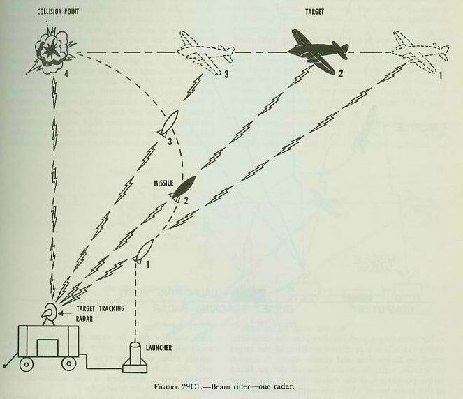
In one type of radar beam-rider system, the target-tracking radar continuously tracks the target. The missile, launched into the beam, continuously seeks out the center of the radar beam until it intercepts the target. In such a system, the missile will fly a changing line-of-sight course to the target, especially when the target is flying a crossing course as illustrated in figure 29C1. Because the radar beam must continuously be directed at and moved with the target, such a flight path possesses the disadvantage of requiring extremely high traverse accelerations of the missile.
The disadvantage of the one-radar beam-rider system is overcome by another system employing two radars and a computer. The target-tracking radar feeds target position data into the computer, which calculates a predicted position of the target based on target data and missile data. A second, or missile, radar is pointed toward the predicted target position, and the missile follows the center of this radar beam, which also supplies missile data to the computer. If the target does not maneuver, and if the calculation of the predicted point is correct, the missile radar beam does not need to be moved from the predicted point; then the missile will fly a straight-line course toward collision with the target as indicated in figure 29C2. If the target maneuvers, or if the computation of the predicted point is in error, the predicted point, and hence the direction of the missile radar beam, will change. Such changes may be expected to be relatively small and to require lower accelerations of the missile than with the type of system employing only one radar beam. The disadvantage of the second system described is the additional complicated equipment involved.

The beam-rider guidance system is especially adaptable for use against incoming air targets, and thus can be expected to be used for AA defense of ships at sea and of cities on land. A number of missiles can be launched into the beam at once, and if the targets aren’t too widely separated, the beam can be shifted to a new target with missiles already in the beam. Accuracy decreases with an increase in range, however, due to the spreading of the radar beam at the longer ranges. As with the command guidance system, possible guidance ranges with present-day radar beam-rider systems are from 75 to 100 miles.
29C9. Homing guidance system
A homing guidance system is one in which the direction of the missile can be changed by a device within the missile which reacts to some distinguishing characteristic of the target. Basically, a homing system consists of a seeker or scanner in the missile which automatically keeps “locked on” or pointed at some special characteristic of the target. The seeker must also send target data to a missile computer which computes signals to cause the attitude control system to keep the missile headed on the correct flight path to intercept the target. The important target characteristics which provide a means for the missile to pick out or keep “locked on” the target are: light emissions, radio emissions, radar reflectivity, infrared (heat) emissions, sound emissions, capacitive features, and magnetic features. To date, the best means of target detection has been through infrared (heat) emissions and radar reflections. These systems are sufficiently accurate that collision may be expected.
In homing systems, the missile must carry all of the equipment and, because of the weight factor, will be limited to short-range operation. Since accuracy of this system increases as the missile approaches the source of energy emitted by the target, a homing system is ideal for terminal guidance. For example, a surface-to-air missile might employ beam-rider guidance to within a few miles of the target and infrared homing guidance to impact with the target. In this manner, the inaccuracy of the beam rider at the outer limits of its radar range might be overcome. At present, the missile must be within 30 miles of the target for successful radar homing and within 5 miles of the target for successful infrared homing.
The homing missile may be designed to follow a highly curved flight path (known as the pursuit flight path) resulting from the missile’s longitudinal axis always being pointed toward the target, as illustrated in figure 29C3. This flight path requires extremely high accelerations from the missile, particularly just before it intercepts the target; consequently, the pursuit flight path is most effective against slow-moving or fixed targets. For fast-moving targets, a lead-type flight path, as illustrated in figure 29C4, might be employed. Whereas lower accelerations are required by this flight path, the missile must carry more complicated guidance equipment.
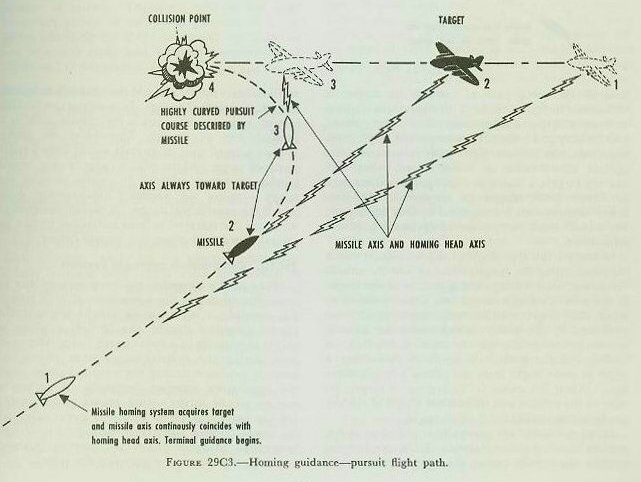
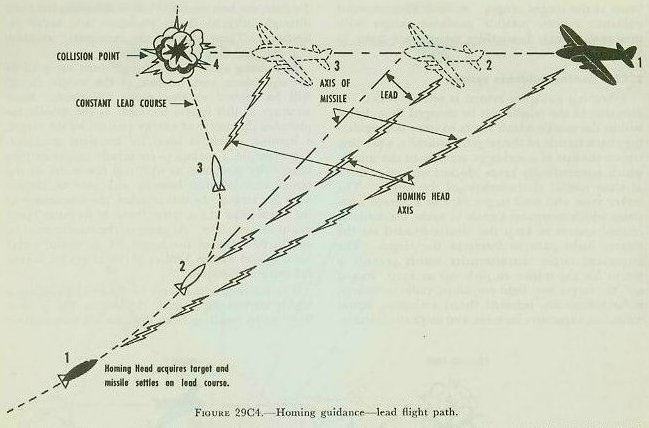
In the pursuit-type flight path, the missile seeker mounted along the longitudinal axis of the missile “locks on” some distinguishing feature of the target. If the missile’s longitudinal axis is not pointed toward the target continuously, error signals are produced by the seeker, which cause the attitude control system to change the missile’s heading. A lead-type flight path will result if the seeker is offset at some angle from the missile’s longitudinal axis. When the seeker is “locked on” a target, the nose of the missile will be pointed ahead of the target by the amount of the offset angle.
Homing systems are generally classified as active, semiactive, or passive systems. In active homing systems, the missile carries the equipment required to illuminate the target, and the system is independent of an external agent. In a semiactive homing system, some agency outside the missile, such as a ground unit or aircraft, illuminates the target. Thus a ground unit or aircraft would keep a radar beam on target and the missile radar receiver would receive the target echoes. In passive homing, the target supplies the necessary illumination upon which the missile will home. A missile designed to home on the infrared or heat radiations from a jet aircraft, or a ship at sea, is a passive homer.
29C10. Combination guidance systems
Many of the foregoing guidance systems may be combined to utilize the advantages of each system. For example, a surface-to-air missile might utilize pre-set guidance during the launching phase to orient the missile in a radar beam, beam-rider guidance during the midcourse guidance phase, and homing guidance during the terminal phase when the beam-rider accuracy decreases. A surface-to-surface missile might utilize pre-set guidance during the launching phase to orient the missile with the target, celestial navigation during the midcourse long-range guidance phase, and homing guidance to enable the missile to pinpoint the target.