Chapter 27 of Naval Ordnance and Gunnery, Volume 2 — Fire Control covers torpedo fire control — the problem of launching a relatively slow underwater missile along the correct course to intercept a moving target. The torpedo fire control problem differs for destroyers, submarines, and aircraft; this chapter treats only the control of torpedoes fired from a destroyer. Consolidated here from the original scanned sub-pages into one illustrated, scrollable page, the chapter covers the general nature of the destroyer torpedo attack, the destroyer torpedo fire control problem (the speed and distance triangles and methods of firing), the destroyer torpedo fire control system (Torpedo Director Mark 27, the torpedo course indicator, and the Torpedo-Tube Mount Sight Mark 5), and the function of the Combat Information Center (CIC) in the radar-aim torpedo attack.
Note on notation: this chapter uses the book’s symbols — St target speed, Sa torpedo speed, A target angle, I track angle, D basic sight angle, D′ corrected sight angle, Br relative target bearing, Car relative torpedo course, Ca true torpedo course, Co own ship’s course, Ct target course, Bur basic tube train, G gyro angle, Q spread angle, Otu tube offset, Osi intercept offset, Gm latitude correction, and Xt and Xa the target and torpedo deflection components.
A. General
27A1. Introduction
The torpedo is recognized as the most effective underwater weapon of naval warfare. It may be fired from submarines, aircraft, or surface vessels. The enormous damage inflicted by torpedoes on our own and enemy forces in the last war is well known. Not so apparent, but still of considerable importance in its effect on tactics, is the constant threat of torpedo attack, present whenever enemy light forces, aircraft, or submarines are known or suspected to be in the vicinity.
The torpedo fire control problem is quite different for destroyers, submarines, and aircraft. In this chapter we will consider only the control of torpedoes fired from a destroyer. The prospective naval aviator or submariner will receive extensive special training in the problem of torpedo fire control from his type of craft.
A primary consideration in a torpedo attack is doctrine, for, if the attack is to be coordinated, all ships participating must act in accordance with the same principles. The successful execution of the mission may be dependent upon how thoroughly the various ships adhere to doctrine. Since torpedo attacks may be made under all conditions of visibility, provisions must be made for establishing the LOS both optically and by radar. Commanding officers, CIC evaluators, torpedo fire control officers, and all torpedo personnel must be thoroughly cognizant of such phases of the doctrine as may apply to them and their stations.
A destroyer torpedo attack will usually be detected by the target ship in the early stages; therefore the torpedoes must be fired at comparatively long ranges. Unfortunately, this gives the target time to maneuver so as to avoid being hit. For this reason, destroyers usually fire several torpedoes in rapid succession in a spread pattern (see art. 27B3). This procedure greatly increases the possibility of obtaining a hit. A division of destroyers in battle usually fires its torpedoes as a unit, with each ship firing a spread. This combination of spreads produces a pattern which is almost certain to give some hits. With spread firing it is possible to neglect certain minor errors which would have to be considered if a single torpedo were fired to hit a given point of aim.
B. Destroyer Torpedo Fire Control Problem
27B1. The torpedo speed triangle
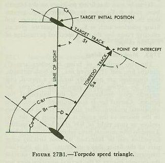
Before proceeding with a study of the fire control instruments and methods of controlling torpedo fire, certain basic elements in the problem must be understood. Figure 27B1 is the basic speed or vector triangle of torpedo fire. It is a graphic representation of the intercept problem in which the torpedo is directed along the correct course to hit the target. Definitions associated with this triangle are as follows:
1. Firing point. The point where the torpedo begins its run; broadly the position of the firing ship when the torpedo is launched.
2. Point of aim. The desired point on the target to be hit with the torpedo.
3. Point of intercept. The point where the torpedo hits the target or crosses the target’s track (or target’s track extended).
4. Line of sight. The straight line from the axis of rotation of the torpedo director to the point of aim on the target.
5. Target speed, St. Speed of the target in knots.
6. Torpedo speed, Sa. The average speed in knots of the actual torpedo from the tube muzzle to the point of intercept.
7. Target angle, A. The relative bearing of the firing ship from the target. Target angle is measured clockwise from the target’s bow to the line of sight between target and firing ship. (A = B + 180° − Ct.)
8. Track angle, I. The angle at the point of intercept between the target’s course and the reverse course of the torpedo, measured clockwise from the target’s course. The ideal track angle is usually considered to be 90° or 270°, because under such conditions the target ship is squarely broadside to the torpedo track, thus offering the largest target area.
9. Basic sight angle, D. The computed angle from the line of sight to the final track of the torpedo, measured clockwise. It must be emphasized that D is independent of range; it is, however, dependent on torpedo speed, which must be decreased if ranges are excessively long.
The sight-angle solution is affected by the following factors:
a. Line of sight — determined visually or by radar.
b. Target angle or target course — estimated or found by tracking.
c. Target speed — determined by eye estimate, or by tracking.
d. Torpedo speed — known in advance from the speed setting ordered.
27B2. The torpedo distance triangle
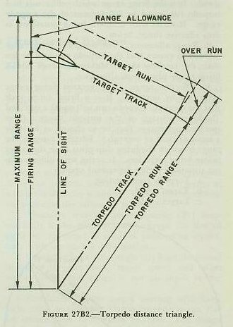
The speed and distance triangles of torpedo fire are similar and may be superimposed. However, it is important for the student to recognize that these two triangles are constructed with different scales, and therefore must be used independently in the two parts of the problem. The distance triangle is shown in figure 27B2. Definitions associated with the distance triangle are as follows:
1. Torpedo track. The line along which the torpedo travels through the water after it has steadied on its set course.
2. Target track. The line along which the target is moving.
3. Torpedo range. The distance in yards which a torpedo is designed to travel before its speed falls off.
4. Torpedo run. The distance in yards which the torpedo travels from the firing point to the point at which it crosses the target’s track (or target’s track extended).
5. Target run. The distance run by the target during the time of torpedo run.
6. Overrun. The distance in yards which a torpedo will run at its designed speed after crossing the target’s track, (or track extended). Torpedo range equals torpedo run plus overrun.
7. Firing range. The distance in yards between the firing ship and the target at the instant of firing.
8. Maximum range. The greatest firing range at which a torpedo may be fired and have sufficient endurance to intercept the target at its designed speed. It is the firing range which will result in a torpedo run equal to 100 percent of the torpedo range. It varies with different firing situations, as does effective range, below.
9. Range allowance. The margin of firing range allowed to ensure that the torpedo run will be less than the torpedo range. Maximum range equals firing range plus range allowance.
10. Effective range. The greatest firing range permitted by doctrine. It is a firing range such that the resultant torpedo run will equal a specified (high) percentage of the torpedo range. (The specified percentage may be so chosen as to leave a small amount of overrun.) Effective range is the range to which the firing ship must close the target before firing torpedoes. It varies with different firing situations, being dependent upon:
a. Torpedo speed setting.
b. Target speed.
c. Target angle.
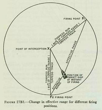
Figure 27B3 illustrates the effective range circle of torpedo fire. The line TX represents the distance and direction the target will travel while the torpedo travels a specified percentage (as in 10 above) of its designed range. The circle represents the locus of all firing positions for an effective range shot for the particular target speed and torpedo speed on which the diagram is based.
It can be seen that firing positions on the target’s bow, such as F1, give an effective range greater than the specified percentage of torpedo range, and firing positions such as F2, on the quarter, give an effective range less than the specified percentage of torpedo range.
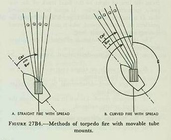
27B3. Methods of firing
The two methods of firing torpedoes are: (1) straight fire, and (2) curved fire. In both methods, the torpedoes are normally fired in a spread, produced by setting small angular offsets onto the torpedo gyro mechanism of the individual torpedoes. Curved fire is accomplished by setting an additional uniform offset angle on all the torpedoes in the mount to the angle it is desired for the torpedoes to turn right or left after being launched. Torpedo-tube mounts have limited sectors in which torpedoes can be launched without striking some part of the firing ship’s structure. It is therefore frequently necessary to use curved fire to unmask the torpedo battery if the tactical situation does not permit changing course. The two methods of firing torpedoes are shown in figure 27B4, along with further elements of the torpedo control problem. Definitions associated with these figures are as follows:
1. Basic tube train, Bur. The computed angle between the fore-and-aft axis of the firing ship and the axis of the torpedo-tube mount, measured clockwise from the firing ship’s bow.
2. True torpedo course, Ca. The angle between the north-south line and the final mean track of the actual torpedoes, measured clockwise from north.
3. Relative torpedo course, Car. The angle between the fore-and-aft axis of the firing ship and the final mean track of the actual torpedoes, measured clockwise from the firing ship’s bow.
4. Gyro angle, G. The angle between the axis of the torpedo-tube mount and the final mean track of the torpedoes, measured clockwise from the axis of the tube mount.
5. Spread angle, Q. The angular difference between the final track of two adjacent torpedoes fired from the same tube mount, after algebraic addition of any angular change caused by relative target motion during the firing interval.
C. Destroyer Torpedo Fire Control System
27C1. Torpedo fire control
Torpedo fire control is a subdivision of fire control and comprises the system of directing the launching of a ship’s torpedoes. It includes material, personnel, communications, and organization. It deals with the launching of a relatively slow missile through the water on the correct course to intercept a target. The functions of torpedo fire control are as follows:
1. Determination or estimation of target motion.
2. Selection of torpedo settings for speed and depth.
3. Determination of sight angle.
4. Determination of spread plan and offsets.
5. Aiming.
6. Tube laying.
7. Firing.
27C2. The control of firing
The two kinds of control used for torpedo fire are: (1) bridge control, and (2) local control. Bridge control is remote control from directors. This is the primary method of control on modern destroyers. The torpedo fire control problem is solved at the torpedo director, in conjunction with information from CIC. Relative torpedo course and basic gyro-angle orders are transmitted electrically from the director to indicators at the tube mount, and the mount is properly trained by matching dials. The director continues to solve the problem during the intervals between the firing of several torpedoes, thus creating a small additional variation between the tracks of the several torpedoes. Local control is accomplished at the tube mount, and is normally used when the director control system is inoperative. In this method, the torpedo fire control problem is usually solved by means of the torpedo-tube mount sight. The sight is offset properly, and then the tube is trained until the sight is on the point of aim. Spreads may be fired by setting spread angles on the torpedo gyros or by varying the point of aim.
27C3. The Torpedo Director Mark 27
Most destroyers are fitted with two Torpedo Directors Mark 27 mounted on the wings of the signal bridge, one on each side; and either of these directors may control the fire of the single centerline quintuple-tube mount usually installed. As mentioned in chapter 21, proper alignment of the torpedo fire control system is a prerequisite to an accurate solution of the problem. The primary function of the torpedo director is to control one or more tube mounts by electrically indicating to them the torpedo course for hitting the target at which the director is aimed. To do this, the director performs the following functions:
1. Measures relative target bearing (Br) automatically if the director trainer keeps the line of sight on the target or matches pointers in accordance with designated information.
2. Computes basic sight angle (D) from the initial inputs of torpedo speed, target speed, and target angle. (Note that range is not an input to the director.)
3. Combines relative target bearing with basic sight angle to produce relative torpedo course Car for transmission to the tube mounts. The design of the director makes it possible for spread angles, latitude correction, and aiming corrections to be applied to Car prior to transmission to the mounts, as will be described later.
The principal parts of the Mark 27 director are: (1) the stand, (2) the case, (3) the telescope unit. See figures 27C1 and 27C2. The stand is bolted to the deck and supports the case on ball bearings. A training circle secured to the stand meshes with a gear driven by the training handwheel mounted on the case. Rotation of the training handwheel turns the case with respect to the stand.
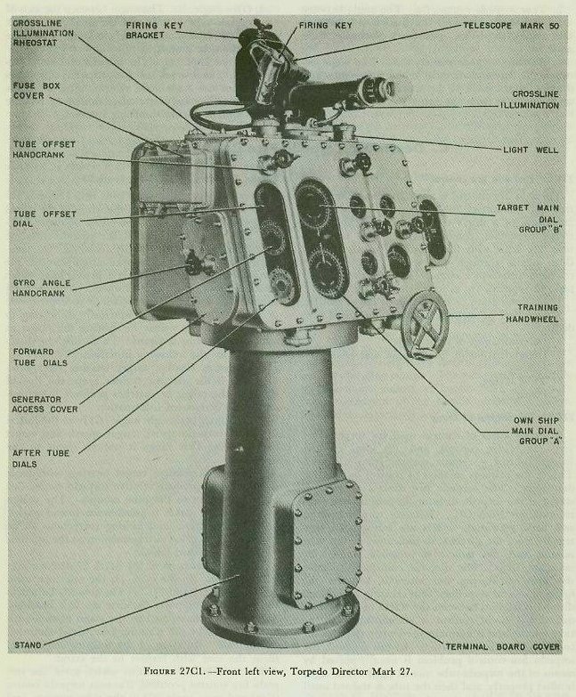
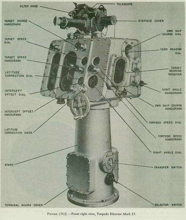
The case houses the units which solve the torpedo fire control problem, transmit torpedo course (Car) and gyro angle (G) to the tube mounts, and receive own ship’s course (Co) from the gyro compass. The knobs for hand inputs and all dials are attached to the case. All inputs are manual except own ship’s course (Co), and if the automatic transmission fails, the Co knob can be used to introduce this value manually.
The telescope unit is normally positioned by a servo follow-up motor within the case. This may also be done manually with the sight-angle crank, on the right side of the case. The Telescope Mark 50 consists of a tiltable mirror and fixed-prism telescope mounted on a pivot. The tiltable mirror makes it possible to hold the line of sight on the target as the ship rolls and pitches. The pivot is supported on a ball-bearing assembly attached to the top of the case. It is geared to the computing mechanism within the case and is automatically turned with respect to the case through the computed sight angle.
27C4. The director solution
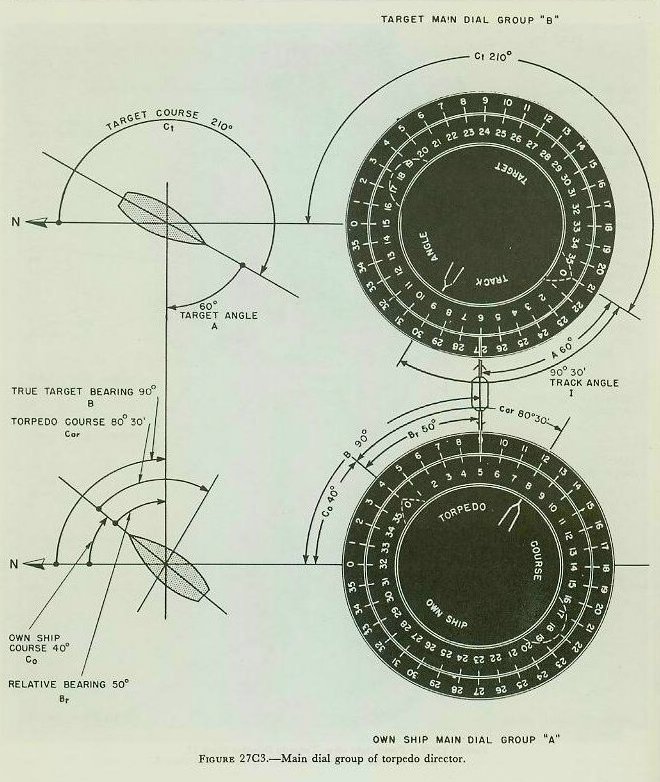
In solving the torpedo problem by a director the initial set-up is made by (1) making manual settings of St, Sa, Ct or A, (and of Co if not received electrically) (2) receiving own ship’s course Co electrically, and (3) keeping the telescope line of sight on the target. The introduction of these settings will set up on the main dial group of the director a picture such as shown in figure 27C3. In each dial group the outer ring is a compass ring, the middle ring represents the ship (own ship in group A, target ship in group B), and the central ring represents the torpedo track in relation to own ship and target. The director solves for sight angle by the principle of equal deflections, in which torpedo deflection (Xa) must equal target deflection (Xt). Then, since Xt = St sin A and Xa = Sa sin D, sin D equals St sin A / Sa.
sin D = (St sin A) ÷ Sa
Figure 27C4 (A) shows the elements of the firing-ship-target set-up and figure 27C4 (B) shows how two component solvers are used to solve for D. In this elementary solution, gyro angle, latitude correction, intercept and tube offsets, and spread angles are not considered. The target solver, from inputs of target course, target speed, own-ship course, and relative target bearing, produces Xt (target deflection component). The sight-angle solver, with an input of torpedo speed, is rotated through an angle of D (sight angle) by the sight-angle servo motor or the sight-angle hand crank, until its output, Xa (torpedo deflection) equals Xt. When Xt equals Xa, the zero-reader dials in the torpedo director are matched.
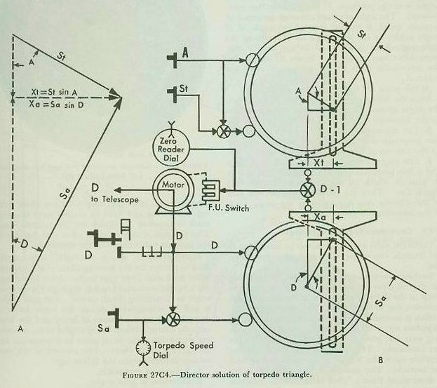
At this point the following relationships exist:
1. Since the telescope LOS is directed at the target, the angle measured clockwise from the ship’s bow to the telescope axis is relative target bearing Br.
2. The telescope unit has been offset from the line perpendicular to the face of the director case by the amount of basic sight angle D.
3. The angle between the bow of the firing ship and a line perpendicular to the face of the case is Br plus D, which (if corrections be disregarded) equals Car. Thus the perpendicular to the face of the director case is parallel to the mean track of the torpedoes.
27C5. Corrections to basic sight angle
Corrected sight angle is obtained by modifying D for latitude correction, Gm, and intercept offset, Osi.
Latitude correction, set manually, compensates for the inherent tendency of the torpedo gyro to creep to the right in north and to the left in south latitudes, due to the rotation of the earth. (No correction is necessary unless the latitude in which the torpedoes are to be fired differs from that at which they were last proved or at which their gyros were last balanced.) The magnitude of the correction depends upon the length of the torpedo run and the latitude. The amount of correction necessary is determined from a “click table” which indicates the number of clicks of the latitude-correction knob required to correct for the latitude in question. Each click moves the dial 10 minutes.
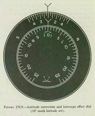
Figure 27C5 shows the latitude correction and intercept offset dial. The outer ring is used for latitude settings and the inner dial for setting intercept offset. In the figure, 10° south latitude correction has been set by rotating the outer ring, causing the S portion to lie opposite the fixed index.
The intercept offset dial does not move while making this setting and must be rotated until the zero mark is opposite the index on the latitude ring. This rotation of the intercept offset dial introduces the latitude correction into the director.
Intercept offset, set in manually, is primarily used to correct for the turning circle of the torpedo when fired with large gyro angle. After launching, the torpedo turns right or left through the set gyro angle to its running (final) course. The gyro angle, it will be remembered, equals the angle between the tube axis at the instant of firing and the final torpedo course. When firing angled shots, an aiming correction must be applied to compensate for the turning circle effect. The amount of this correction depends upon the following:
1. Amount of gyro angle.
2. Direction of gyro angle.
3. Speed setting of the torpedo.
4. Run of the torpedo to intercept point.
5. The mark of the torpedo.
Tables are provided showing the amount of this correction for various combinations of the above variables. The correction taken from the table is to be applied by turning the intercept offset knob in the same direction as the applied gyro angle, through the amount of the correction. This will turn the inner dial, figure 27C5, right or left in accordance with the markings R and L.
The setting of intercept offset is not made until the latitude setting has been completed with the intercept offset dial zeroed on the fixed index of the latitude ring. If this procedure were not followed, erroneous inputs would result.
Another use of the intercept offset dial is to provide a small variation in sight angle to compensate for expected target maneuvers in attempting to avoid the torpedoes. In the case shown in various figures in this chapter, the target may be expected to turn toward the oncoming torpedoes, in an attempt to parallel the torpedo tracks. The intercept offset knob could be used to decrease by a small amount the computed value of sight angle, in order to nullify the effect of this maneuver.
Basic sight angle as corrected by Gm and Osi constitutes corrected sight angle, D′. This quantity, added to Br, produces Car, which is the primary output to the torpedo course indicator at the tube mount.
27C6. Determination of basic tube train
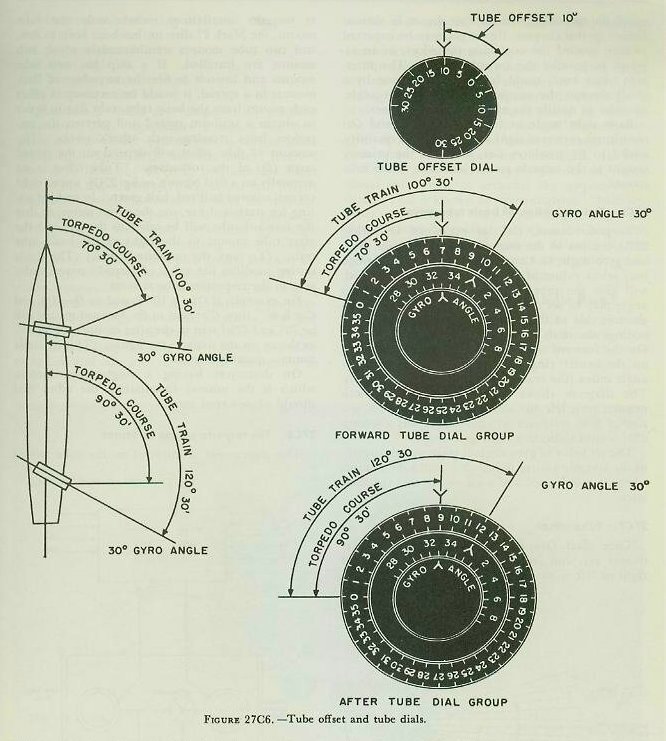
Torpedo course, Car, as explained in article 27B3 consists of the sum of basic tube train, Bur, and gyro angle, G. Control personnel on the bridge may select values of Bur and G which, combined, will give the proper value of Car, because gyro angle may be set manually by means of a crank in the left side of the director case. In making the settings the dials shown in figure 27C6 are used. On the forward tube dial group, gyro angle is set on the center ring dial opposite the fixed gyro angle index (the reading shown being 330 degrees). The diagram shows how torpedoes from both mounts turn left 30° to their final course. A setting of 360° indicates zero gyro-angle set; a setting 030° would indicate a right gyro angle.
The set value of gyro angle is transmitted directly to the torpedo course indicator at the tube mount, where it is indicated and used as will be explained later.
27C7. Tube offset
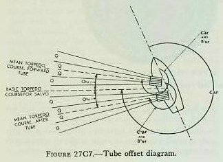
Tube offset, Otu, is the angle between the tube-mount axis and basic tube train (Bur), measured right or left from Bur. Although modern destroyer torpedo installations include only one tube mount, the Mark 27 director has been built to control two tube mounts simultaneously where two mounts are installed. If a ship has two tube mounts and intends to fire the torpedoes of both mounts in a spread, it would be necessary to offset each mount from the basic tube train Bur in order to obtain a uniform spread and prevent the torpedoes from crossing each other’s tracks. The amount of tube offset will depend on the spread angle (Q) of the torpedoes. Tube offset is set manually on a dial (shown in fig. 27C6, upper right corner) colored half red, half green. In making setting for starboard fire, use the green sector, so that the forward tube will be offset to the left and the after tube mount to the right of the basic tube train. (To port, the opposite is true.) The single setting modifies the value of torpedo course order sent to the respective tube mounts.
For example, if Otu is 10° (based on Q = 4°), and Car is 80°, then C′ar sent to the forward mount will be 70° and C′ar sent to the after mount will be 90°, as shown on the dials in the figure. (This example assumes quintuple tubes.)
On destroyers having a single tube mount, which is the normal installation, the offset dial should always read zero.
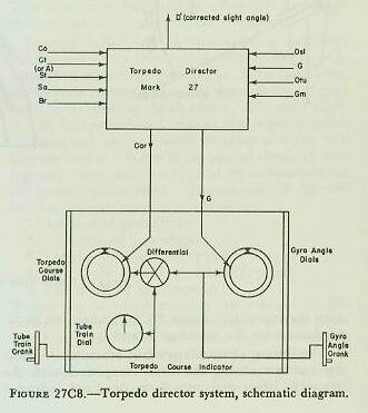
27C8. The torpedo course indicator
This instrument is installed on the tube mount and indicates the following values:
1. Actual tube-mount train.
2. Gyro angle ordered.
3. Gyro angle set.
4. Torpedo course ordered.
5. Torpedo course set.
Quantities 2 and 3 are compared on a follow-the-pointer dial. Quantities 4 and 5 are compared on zero-reader and follow-the-pointer dials. Referring to figure 27C9, torpedo course, received electrically from the director, positions the inner dial of the torpedo-course dials at the left. Gyro-angle order, received electrically from the director, likewise positions the inner dial of the gyro-angle dial group at the right. Matching gyro-angle order is accomplished by rotating the gyro-angle hand crank on the mount; this action also sets the gyro angle on the torpedo gyros to agree with the value transmitted by the director. This setting also goes through a differential, partially positioning the outer (ring) dial of the torpedo-course dial group. As the mount is trained, actual tube train from the auxiliary training rack positions the tube-train dial and also goes through the differential to match the torpedo-course dials. Thus torpedo course for torpedoes fired from a tube mount equals mount train plus gyro angle.
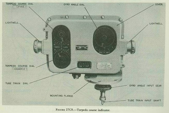
The tube-train dial is painted red in the danger sectors, and yellow in the adjacent 10° sectors, providing the tube trainer with suitable warning. If, after matching torpedo-course dials, he observes the tube train dial to be “in the red,” he must train clear of the danger sector, which will cause the torpedo-course dials to become unmatched. He then orders the gyro setter to apply the necessary additional gyro angle to rematch the torpedo-course dials. This is known as “gyro-angling.” Intercept offset correction for this additional gyro angle will not, of course, be applied; but when it is imperative that torpedoes be fired without delay, it is thus possible to modify a director solution which would put the tube on a danger bearing.
27C9. The Torpedo-Tube Mount Sight Mark 5
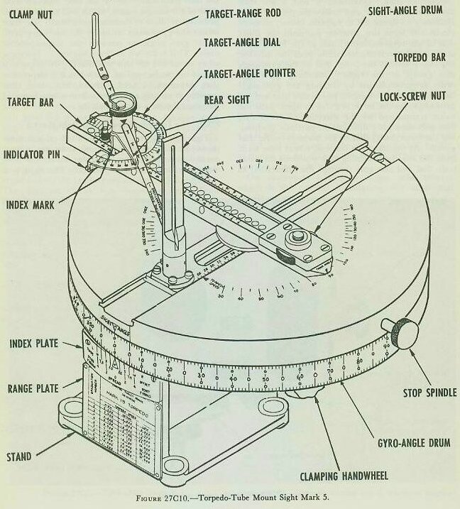
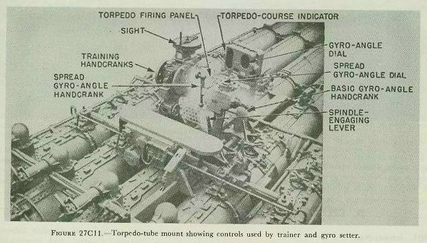
This sight, figure 27C10, installed on the tube-mount training handwheel stand, is for use in local control of torpedo fire. Its location on the tube mount is shown in figure 27C11. The sight is a combination director and aiming device and consists of two concentric rotatable plates. The upper plate carries pivoted and sliding bars which can be set to reproduce the speed triangle of torpedo fire from inputs of A, St, and Sa. These inputs offset the sight bar by the correct D. Then when the sight is aimed at the target, the mount is correctly trained to lead the target. Gyro angle may be introduced by rotating the lower plate to the desired G, moving the upper plate with it to introduce this further offset to the sight.
When D is computed by the Mark 27 director, its value phoned to the mount, and the tube-mount sight used only for aiming, the control is called “local aim of bridge control.” In this use of the Mark 5 sight, the pivoting and sliding bars are not set up as previously described. Instead, the upper plate is rotated to the ordered D, offsetting the sight bar (line of sight) from the tube-mount’s axis.
27C10. Torpedo firing and ready light system
The purpose of this system is to provide electrical firing of each barrel, controlled from the bridge. The control features of the system are as follows:
1. The bridge firing panel. One bridge firing panel is installed near the director for each tube mount. It contains the tube-mount ready light and a selector switch for each barrel.
2. The mount firing panel. A mount firing panel is installed on the tube mount near the trainer’s position. It contains a switch which closes or opens all the firing circuits on the mount. When this switch is closed, it also lights the mount ready light in the bridge panel.
3. The firing key. There is a firing key mounted on the director. An auxiliary bridge key may be plugged in if needed. No electrical firing can take place unless one of these keys is closed.
27C11. The torpedo-tube mount
The following features of the torpedo-tube mount enter into the control problem:
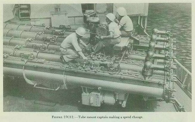
1. The gyro-setting mechanism. This permits setting both gyro angle (G) and spread angle (Q). The gyro spindle-engaging lever is moved to the IN position, causing a vertical spindle to extend through each barrel from the bottom and engage the gyro-setting mechanism of the torpedoes. The gyro-angle hand crank is rotated until the desired angle is indicated on the gyro dials. This sets the same gyro angle, G, on each torpedo, and this value appears on the torpedo-course indicator. Another hand crank, the spread-angle setting hand crank, is rotated until the desired spread angle (Q) is indicated on a dial on the hand-wheel pedestal. This produces different gyro settings on individual torpedoes, so that they will fan out from the center torpedo with a separation of Q degrees.
2. The depth-setting mechanism. This permits setting the depth at which the torpedoes are to run. The depth-setting socket lever is placed in the IN position, causing a vertical shaft, fitted with a socket on its end, to extend through each barrel from the top and engage the depth-setting mechanisms of the torpedoes. The hand crank is then rotated until the desired depth setting is indicated on the dial.
(Gyro-setting spindles and depth-setting socket levers must be in the out position when loading or unloading torpedoes from the tubes, and prior to launching, for obvious reasons.)
3. Torpedo speed setting. This is set by engaging a spring-loaded spindle in each barrel of the tube mount with the speed-setting mechanism of the torpedo. Each spindle is rotated by hand to the HIGH, INTERMEDIATE, or LOW position as indicated by the index pointer, and is then released. The spring will then automatically disengage the spindle from the torpedo speed-setting mechanism.
D. CIC’s Function in the Radar-Aim Torpedo Attack
27D1. Introduction
The radar-aim, director-controlled, destroyer torpedo attack became highly developed during World War II. In any discussion of torpedo fire control, we must therefore include this type of attack and the function of CIC in making it. The line of sight to the target is established by the torpedo-director trainer, keeping follow-the-pointer bearing dials matched in the bearing repeater located on the right side of the Mark 27 torpedo director (see fig. 27C2). By means of a selector switch, target bearing may be received by this repeater either from the fire control radar, or from search radar. Fire control radar bearings are preferred, as they provide greater accuracy.
27D2. Shipboard stations active in the radar-aim torpedo attack
The conning station, main-battery director (Director Mark 37), plotting room, Combat Information Center, Torpedo Control, and torpedo-tube mount all have important functions in delivering the radar-aim torpedo attack.
CIC tracks the target, designates the target to the main-battery director, keeps Conn and Torpedo Control informed of all target movements, and checks the solution of target course and speed with the plotting-room computer solution. Initially, CIC must give Conn a course to an approach point which will put the ship in good position to make an attack. This approach point is usually a general location approximately 30° to 40° on the target’s nearest bow just outside the effective range of the torpedo to be fired. Upon reaching the approach point, CIC recommends a firing course to Conn which will keep the target within effective range for a reasonable period of time and allow a firing bearing which will produce the optimum track angle of approximately 090 degrees or 270 degrees. When the ship on the firing course approaches the firing bearing, CIC so informs the captain and requests permission to fire torpedoes. Torpedo Control, on the command of CIC, fires torpedoes upon reaching the firing bearing.
In this method CIC obtains target course and speed from the DRT (dead-reckoning tracer) and figures approach and firing courses and firing bearing with the maneuvering board. The main-battery director (Director Mark 37) stays trained on the target by radar. The Computer Mark 1A in the plotting room solves for target course and speed as a check on the DRT.
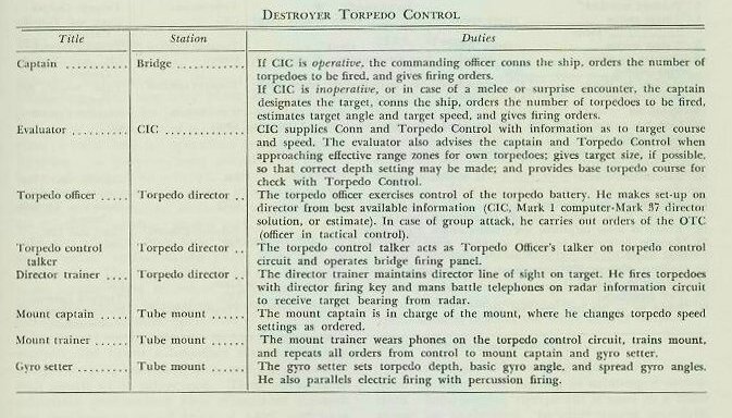
27D3. Typical destroyer torpedo control set-up
The following table may be taken as typical:
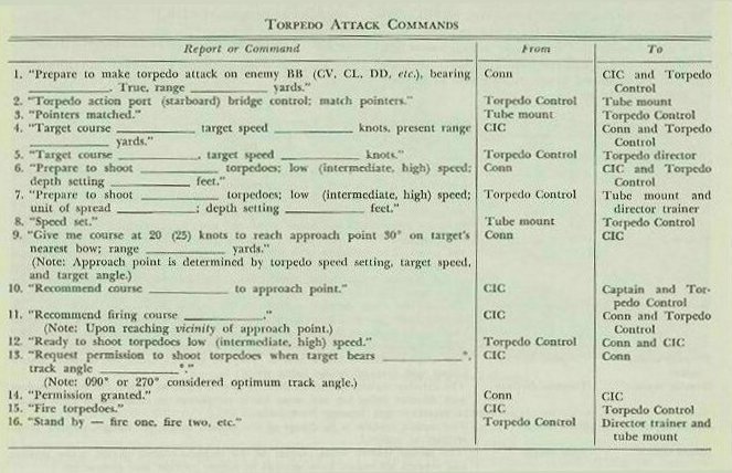
27D4. Standard commands
The following procedure is for radar-aim, director control, destroyer torpedo attack.
It is assumed that a contact has been picked up, identified as enemy, and that the decision to attack with torpedoes has been made: