
Chapter 26 of Naval Ordnance and Gunnery, Volume 2 — Fire Control covers relative-rate antiaircraft fire control systems — the lead-computing sights and director systems developed to solve the AA problem at short and intermediate ranges, where solution time must be very short. Unlike the linear-rate Mark 37 (chapter 25), these systems measure the angular velocity of the line of sight directly, by gyroscopic means. Consolidated here from the original scanned sub-pages into one illustrated, scrollable page, the chapter treats the fire control problem, the basic elements of lead-computing sights, Gun Sight Mark 15, Gun Fire Control System Mark 63, and Gun Fire Control System Mark 56.
Note on notation: this chapter uses the book’s symbols — dE and dBs the angular rates of the line of sight in elevation and traverse, dR the range rate, R present range, RdE and RdBs the corresponding linear rates, V and D the elevation and traverse lead angles, E′b director elevation, B′r′ director train, and primed quantities (E′g, B′gr, V′d, D′d) values referred to deck coordinates.
A. The Fire Control Problem
26A1. Introduction
Increased aircraft speeds in World War II made necessary the development of fire control systems which could further reduce the time required for solution of the antiaircraft fire control problem. This step was vitally necessary for the control of machine guns, for which the solution time is limited by the relatively short effective range of the weapons. Inasmuch as an individual system is provided to control each mount, the fire control system had to be limited in size and weight. Furthermore, since the greatest danger to the ship was from incoming targets at close ranges, many of the factors computed by such a fire control system as the Mark 37 could safely be ignored. The result was the development of a family of lead-computing or relative-rate systems which differ from the Mark 37 fire control system in that they measure the rates of change of bearing and elevation directly as angular quantities, and measure these quantities simply by tracking the target. Although originally used for machine guns, systems of this type have now been developed to control guns as large as 6-inch at close and intermediate ranges.
Some relative-rate systems offset the line of sight from the fore-and-aft axis of the sight case by the amount of computed lead angle, so that the sight case itself is aligned with the gun bore axis. These systems are known as disturbed-line-of-sight systems. Most lead-computing sights are of this type. Other systems, however, measure the lead angles and transmit them to a computer which makes up the gun orders, while leaving the sight telescope, fixed in relation to the sight case, in the line of sight. These are known as undisturbed-line-of-sight systems.
Gun Sight Mark 15 and Gun Fire Control System Mark 63, which are examples of disturbed-line-of-sight systems, are described in some detail in this chapter.
26A2. Lead angles
The hunter who shoots ducks on the wing knows that he must lead the duck by a sufficient angle to compensate for the duck’s travel while the load of shot is in the air. A moment’s reflection will show that if the duck is climbing, the hunter must lead in elevation; if it is flying across the hunter’s line of sight, there must be a lead angle across the line of sight, in traverse. The actual lead angle is the resultant of these two components.
Lead angles in AA fire are analogous. Tracking the usual air target calls for lead in both traverse and elevation to compensate for target motion during time of flight. This may be illustrated by pointing a finger at a flying airplane and following it for a time. The rate at which the finger moves in following the flight of the plane is a rough measure of the angular velocity of the line of sight. The angular velocity of the line of sight, when measured accurately and adjusted for time of flight and for ballistic corrections, becomes the total lead angle. More precisely, the total lead angle may be defined as the angle between the line of sight to the present target position and the position of the gun bore axis required to hit the target at the end of the time of flight. This is illustrated in figure 26A1.
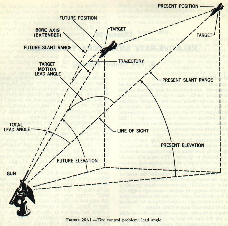
Total lead angle may also be defined as target motion lead angle plus ballistic corrections. Target motion lead angle is the angle between the line of sight to the target’s present position and the line from gun to target at the end of the time of flight. Target motion lead angle is ordinarily made up of an elevation lead angle, measured in a plane perpendicular to the deck, and a traverse lead angle, measured in the traverse plane. The traverse plane is the slant plane containing the gun or sight trunnion axis and the present position of the target. Although the usage is not strictly accurate, the term train, instead of traverse, is usually used for the sake of convenience.
26A3. Superelevation
As shown in figure 26A1, the gun bore cannot be pointed directly at the future target position, because the projectile follows a curved trajectory. A part of this curvature is caused by the downward pull of gravity on the projectile. The correction for this effect is called superelevation. As gravity always acts in a vertical plane, superelevation must be computed in this plane. Superelevation varies with future target range, initial projectile velocity, and future target elevation. Since the force of gravity acts continually on the projectile, the longer the time the projectile is in flight, the greater will be the vertical deviation of the projectile from the gun bore axis. From this it follows that superelevation must vary directly with range, since the time of flight is greater for a greater range. It is also apparent that as initial velocity decreases, superelevation must increase, since a longer time is required for the projectile to reach a given range.
The effect of gravity on the projectile is to pull it down vertically. We are for the time being concerned only with the deviation of the projectile from the line of the gun bore axis, however, and so need consider only that component of gravity which is perpendicular to the gun bore axis. It is readily apparent that this component decreases as target elevation increases, and that for a given range, superelevation varies directly as the cosine of the elevation angle of the gun above the horizontal. The effects of range and elevation on superelevation are illustrated by figure 24B6.
26A4. Drift
A second element of the trajectory’s curvature is drift, which is a projectile’s tendency to move to the right of the extended gun bore axis. Gun barrel rifling causes the projectile to rotate at high speed, thus imparting gyroscopic properties to it. These properties give the projectile a tendency to maintain its axis parallel to the gun bore axis throughout its flight. Since gravity pulls the projectile downward from the line of the gun bore axis, its nose tends to remain elevated above a line tangent to its trajectory. Air resistance against the lower part of the nose of the projectile produces an upward force on the nose. The combination of projectile inertia and air resistance produces a torque which causes the projectile to precess to the right. The effects of drift vary directly with the angle made by the projectile’s centerline with the trajectory and with the projectile’s time of flight. Since a trajectory departs farther from the line of the gun bore axis at low gun elevations than at high elevations (due to superelevation), drift varies inversely with gun elevation or directly with the cosine of gun elevation. Also, since a longer range requires a longer time of flight and greater superelevation, the effects of drift vary directly with range. This means that for very short ranges drift is small, and it may safely be ignored in lead-computing sights which are designed for firing only at these short ranges.
26A5. Other ballistic corrections
The numerous other factors which affect the trajectory, such as wind, air density variations, and the like, are present in the short-range antiaircraft fire control problem, but in many cases they may safely be ignored, just as drift is ignored in the simpler sights. In unusual cases, where these uncorrected factors cause large errors, they may be corrected by spotting with the assistance of tracers. More complex relative-rate sights and systems, designed for firing at longer ranges, do make corrections for some of these factors.
B. Basic Elements of Lead-Computing Sights
26B1. Introduction
In solving the fire control problem for short-range antiaircraft fire, the various lead-computing sights and relative-rate systems make use of a number of elements which are not used in linear-rate systems such as the Mark 37. Three of these elements will be described in this section: the rate-of-turn gyro, the torque motor, and the pick-off transformer.
26B2. Rate-of-turn gyro
It will be recalled from the study of Stable Element Mark 6 that the two basic properties of a free gyroscope are rigidity of its plane of rotation in space and gyroscopic precession. The functioning of lead-computing sights is based on the principle that the precessional torque exerted by the gyro is directly proportional to the force causing the precession. In order to measure angular rates of target motion, lead-computing sights employ restrained gyros of a type known as rate-of-turn gyros.
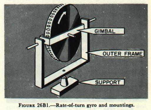
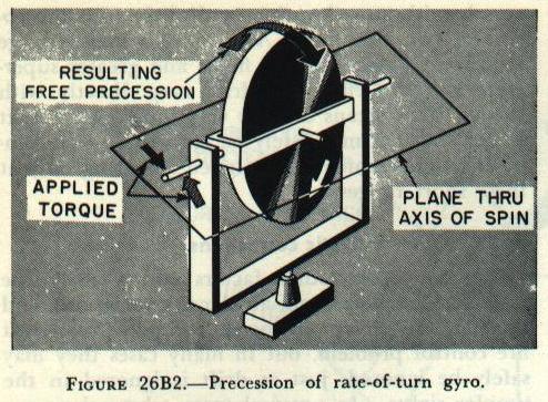
A rate-of-turn gyro has only one gimbal, and therefore only two degrees of freedom. Figure 26B1 shows the essential parts of such a gyro. The wheel is free to turn about the axis of spin, and may precess in its gimbal frame about an axis 90 degrees removed from the axis of spin. When a torque is applied by rotation of the gimbal frame about the input axis as shown by figure 26B2, the gyro will precess, or tilt, and will continue to do so as long as the motion continues. Actually, this gyro is mechanically restrained by springs of known stiffness.
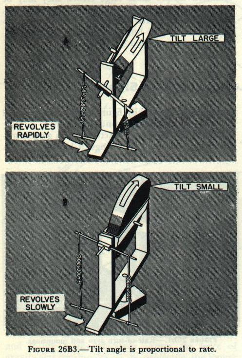
One method by which this might be accomplished is illustrated in figure 26B3. Although the method shown is somewhat simpler than those employed in actual sights, it serves to demonstrate the principle. As soon as the wheel starts to tilt, one spring is extended and the other compressed. The rotor will continue to tilt until the restraining torque exerted by the springs is equal to the precessional torque of the gyro about the output axis. This precessional torque is directly proportional to the rate of turn of the gimbal frame about the input axis. If the gimbal frame is turned rapidly, as in figure 26B3 (A), the gyro rotor will tilt sharply before the two torques are balanced, as in figure 26B3 (A, B). When the gimbal frame is turned more slowly, the rotor tilts to a lesser angle. Since the restraining springs resist the precession of the gyro, the amount of rotor tilt is inversely proportional to the stiffness of the springs. The tilt about the output axis, then, depends upon this relationship:
where K is a constant depending on the stability of the particular gyro.
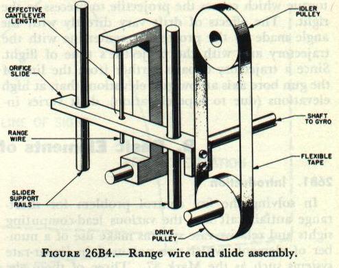
Gun Sight Mark 15, which will be described in this chapter, uses two rate-of-turn gyros having a cantilever type restraining spring, as shown in figure 26B4. The rate-of-turn gyros are used to generate target motion lead angles. The required target motion lead angle is the product of the angular velocity of the line of sight and the time of flight. The gyros are so mounted within the sight case that when the operator is tracking smoothly, the gimbal frame of one gyro turns about its input axis at a rate equal to the angular velocity of the line of sight in elevation, and the gimbal frame of the other gyro turns about its input axis at a rate equal to the angular velocity of the line of sight in traverse. The two gyros are called the elevation gyro and the train gyro, respectively. The stiffness of the restraining springs is adjustable by moving the orifice slide, as may be seen in figure 26B4. The stiffness of these is adjusted in accordance with the time of flight. Since the lead angle must be greater for a longer time of flight, the restraining spring stiffness is made less for a longer time of flight.
Consequently, the rotation of the output shaft is directly proportional to the required lead angle.
It should be stated at this point that Gun Sight Mark 15 is designed for use against high-speed, short-range targets, and is an accurate and dependable system only when so used. It is not suitable for use against targets at long range, for the reason that in such cases the angular bearing rate is so small that tracking cannot set up a dependable solution.
26B3. Torque motor
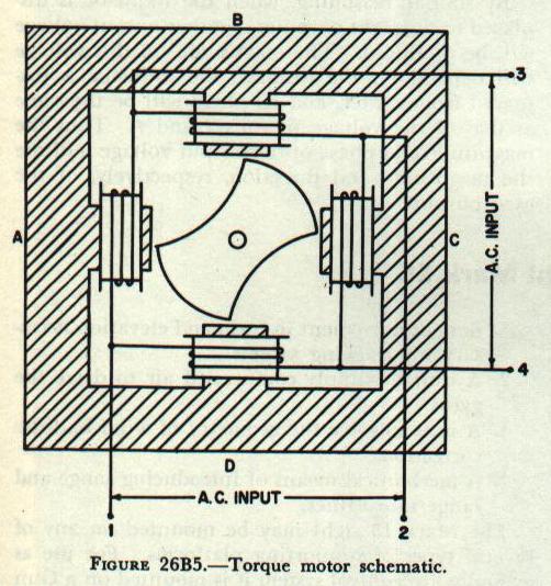
A torque motor is a motor with a rotor shaft that exerts deflecting torques, and is illustrated schematically in figure 26B5. The magnitude and direction of the output torque depend upon the magnitudes and phase relationship of two a-c input potentials impressed upon the motor stator coils.
A torque motor consists of a soft iron rotor mounted within a laminated soft iron stator frame, and four coils mounted 90 degrees apart on the stator. The stator coils are connected to form a closed bridge circuit.
Operation of a torque motor may be understood by the analysis of the currents flowing through the various stator coils and the magnetic fields produced by these currents. If the phase relationship of the two input potentials is such that at a particular instant terminals 1 and 3 are negative and terminals 2 and 4 are positive, the currents in coils B and D will reinforce each other. At the same time, the currents in coils A and C will be opposing each other. Consequently, the magnetic field between poles B and D will be stronger than that between poles A and C. Since the rotor tends to align itself with the magnetic lines of force of the stronger field, it will exert a counterclockwise torque. It should be noted that the rotor is restrained to only a few degrees of rotation, so that it does not completely align itself with poles B and D, but merely exerts a torque in that direction.
Suppose now that the phase of one of the input potentials is reversed, so that at a particular instant terminals 1 and 4 will be negative and terminals 2 and 3 will be positive. In this case the currents in coils B and D will oppose each other, while the currents in coils A and C will reinforce each other. The rotor will now tend to align itself with poles A and C, producing a clockwise torque.
As a third example, let us assume that no voltage is impressed between terminals 3 and 4. Now the currents in all coils will be equal, the magnetic fields will be equal, and no output torque will result.
The output torque in each instance is directly proportional to the product of the magnitudes of the two input potentials, and the direction of the output torque is dependent upon the phase relationship of the two inputs.
In some lead-computing sights, torque motors are employed to modify the lead angles to correct for the effect of wind during the time of flight. This is accomplished by mounting the torque motor so that its rotor is attached to the output shaft of the rate-of-turn gyro. The output torque of the torque motor then either aids or opposes the precessional torque of the gyro, thus modifying the generated lead angles. In this case the input potentials represent wind rates.
26B4. Pick-off transformer

A pick-off transformer is a wire-wound inductive electrical element which is used to convert the mechanical angular displacement of a gyro output shaft into an electrical signal for transmission to other components of a relative-rate system. The electrical output signal defines the magnitude and direction of the gyro shaft output. A pick-off transformer is shown schematically in figure 26B6.
The train and elevation pick-off transformers used in Gun Sight Mark 15 are identical. Each consists of a frame, an inductor, and six coils. Both the frame and the inductor are of laminated, high-permeability steel. Four pole pieces are mounted within the rectangular frame. Two primary coils are wound on the sides of the frame, and four secondary coils are wound on the four pole pieces. The inductor, mounted on an arm attached to the gyro output shaft, moves in the space between the secondary coils.
The pick-off transformer primary windings are connected in series across a 10-volt a-c supply; the secondary coils are connected in series with the output leads. The coils are wound so that the voltages induced in coils 1 and 2 are opposite in phase to those induced in coils 3 and 4. When the inductor is centered, the voltage induced in coils 1 and 2 is equal in magnitude and opposite in phase to that induced in coils 3 and 4. The result is zero output voltage.
When the inductor is moved to the left by rotation of the gyro output shaft, the reluctance (magnetic resistance) of the magnetic path between poles 1 and 2 is less than that of the path between poles 3 and 4. Because a lower reluctance allows a greater magnetic flux, the voltage induced in coils 1 and 2 is greater than that induced in coils 3 and 4. This voltage difference becomes greater as the inductor is moved farther from its center position. The output voltage is now equal to the difference between the voltage induced in coils 1 and 2 and the voltage induced in coils 3 and 4, and has the same phase as the voltage in coils 1 and 2.
By similar reasoning, when the inductor is displaced to the right of center, another output voltage will be produced. The magnitude of this voltage will depend on the distance the inductor is displaced from center, and its phase will be the same as that of the voltage in coils 3 and 4. Thus the magnitude and phase of the output voltage indicate the magnitude and direction, respectively, of the gyro output.
C. Gun Sight Mark 15
26C1. Introduction
Gun Sight Mark 15 is an example of a gyroscopic lead-computing sight which is designed for the control of heavy machine guns and dual-purpose guns at short and intermediate ranges. It may be used against targets with range rates up to 350 knots (800 knots in some modifications) and at ranges up to a maximum of 7,500 yards. In addition to its use as a complete fire control system in itself, Gun Sight Mark 15 is used in some modifications of the Gun Fire Control System Mark 63, which will be described later in this chapter.
26C2. Physical description
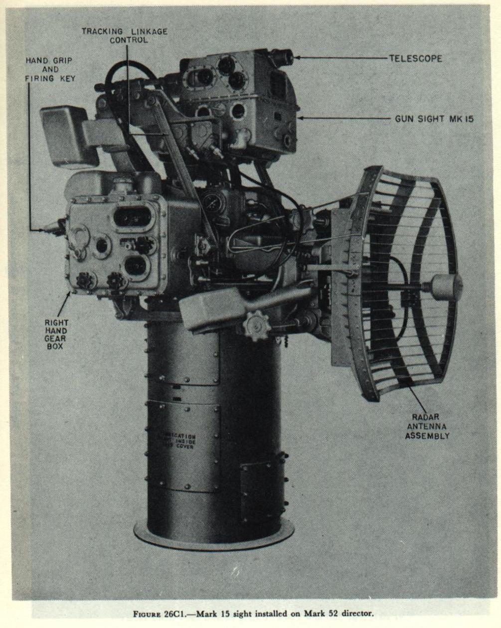

Figure 26C2 shows a mechanical schematic representation of the Mark 15 sight. The entire mechanism shown in this figure is enclosed in a case, which is shown in figure 26C1. In addition to the mechanism contained in the sight case, several other items of equipment are required. These items include:
1. A supporting platform which provides the freedom of movement in train and elevation necessary for tracking targets.
2. A unit to supply compressed air to drive the gyros.
3. A unit to solve the geometry of wind ballistic corrections.
4. A mechanical means of introducing range and range rate values.
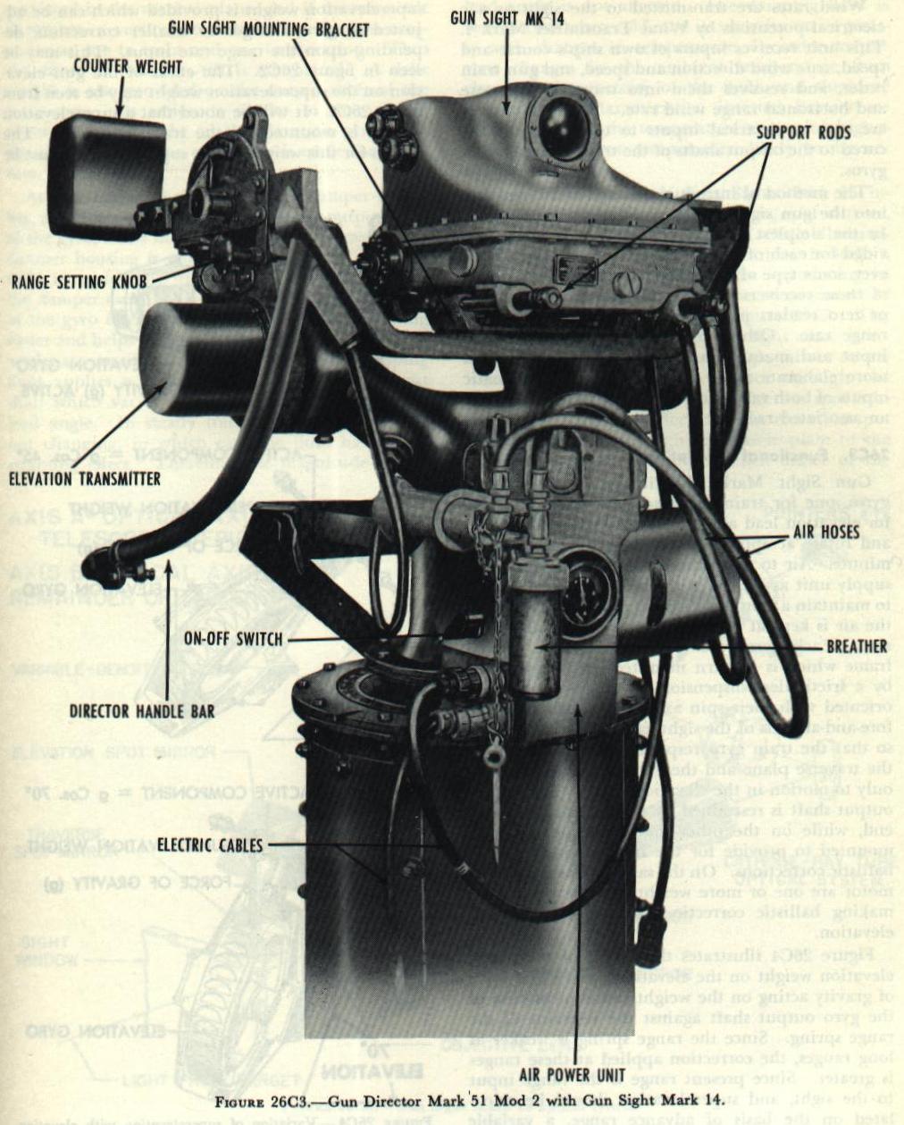
The Mark 15 sight may be mounted on any of several types of supporting platforms. For use as a simple fire control system it is mounted on a Gun Director Mark 51. Such a director is shown in figure 26C3, equipped with a short-range lead-computing sight, the Mark 14, which is somewhat simpler than the Mark 15. For use as a part of a more elaborate system, the sight may be installed on a Mark 52 director, as shown in figure 26C1, or on a Mark 1 director pedestal, as shown schematically in figure 26D1.
An air supply unit is furnished with each sight and installed near the sight. This unit provides a supply of dried, compressed air at a constant pressure to the sight for spinning the rate-of-turn gyros. Wind rates are transmitted to the sight as a-c electrical potentials by Wind Transmitter Mark 4. This unit receives inputs of own ship’s course and speed, true wind direction and speed, and gun train order, and resolves them into traverse wind rate and horizontal range wind rate. These wind rates are sent as electrical inputs to torque motors secured to the output shafts of the train and elevation gyros.
The method of introducing range and range rate into the gun sight varies in different installations. In the simplest arrangement only a knob is provided for each of these inputs. In most cases, however, some type of range receiver is provided. Some of these receivers provide only for matching dials or zero readers manually to introduce range and range rate. Others provide for automatic range input and manual range rate input, while even more elaborate range receivers provide automatic inputs of both range and range rate as received from an associated radar.
26C3. Functional description
The Gun Sight Mark 15 utilizes two rate-of-turn gyros, one for train (traverse) lead angle and one for elevation lead angle. The gyros are air-driven, and rotate at approximately 8,300 revolutions per minute. Air to drive the gyros comes from an air supply unit associated with the sight, and in order to maintain a constant speed of rotation of the gyro, the air is kept at a constant temperature and pressure. Each gyro rotor is mounted in a gimbal frame which is in turn mounted in the gyro case by a frictionless suspension. The gyro rotors are oriented with their spin axes perpendicular to the fore-and-aft axis of the sight case and to each other, so that the train gyro responds only to motion in the traverse plane and the elevation gyro responds only to motion in the elevation plane. Each gyro’s output shaft is restrained by a range spring at one end, while on the other end a torque motor is mounted to provide for the introduction of wind ballistic corrections. On the same end as the torque motor are one or more weights for the purpose of making ballistic corrections for drift and superelevation.
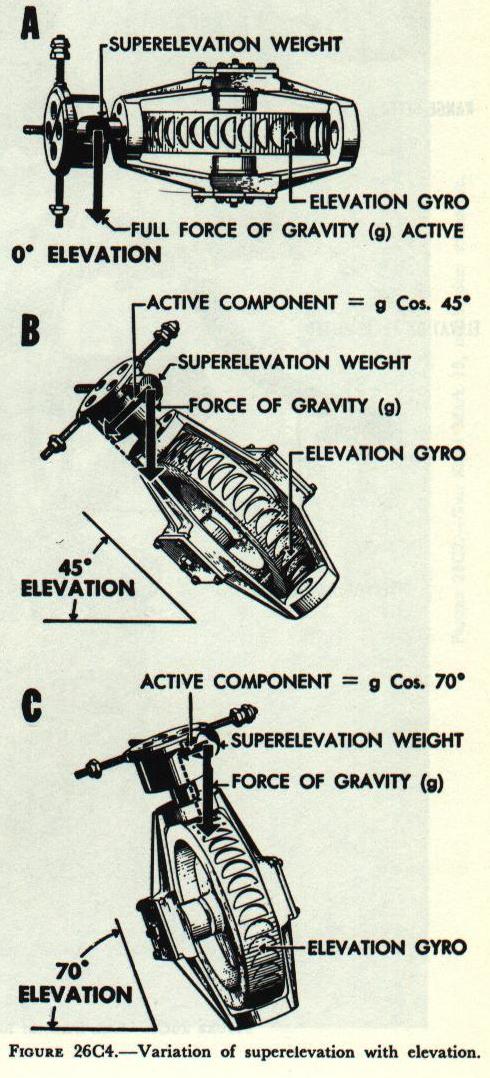
Figure 26C4 illustrates the action of the superelevation weight on the elevation gyro. The force of gravity acting on the weight causes a rotation of the gyro output shaft against the restraint of the range spring. Since the range spring is weaker at long ranges, the correction applied at these ranges is greater. Since present range is the range input to the sight, and superelevation should be calculated on the basis of advance range, a variable superelevation weight is provided which can be adjusted to give a larger or smaller correction, depending upon the range rate input. This may be seen in figure 26C2. The effect of the gun elevation on the superelevation weight may be seen from figure 26C4. It will be noted that a superelevation weight is mounted on the train gyro also. The reason for this weight is that superelevation must be corrected in the vertical plane, and if trunnion tilt is present, a vertical correction requires two components: one in train and one in elevation. Thus the effect of trunnion tilt is eliminated. A drift weight is also provided on the output shaft of the train gyro. Its action is similar to that of the superelevation weight on the elevation gyro, with the exception that no correction is made for range rate.
At each end of the gyro case is a damper assembly, consisting of a disc attached to the output shaft of the gyro, and a housing secured to the case. The damper housing is partially filled with a damping fluid in which the disc rotates. The purpose of the damper assembly is to smooth out the response of the gyro during tracking. This makes tracking easier and helps prevent the generation of false lead angles as a result of tracking errors. The damping fluid applies a restraining torque to the output shaft which varies with the rate of change of the lead angle. In steady tracking the lead angle is not changing, in which case the fluid has no restraining effect. Therefore the magnitude of the lead angle is not affected. The damping fluid is very viscous when cold, and its viscosity varies greatly with changes in temperature. In order to prevent changes in the ambient temperature from changing the viscosity of the fluid, and therefore the damping characteristics, internal heaters are used to stabilize the temperature at a value higher than any ambient temperature likely to be encountered.
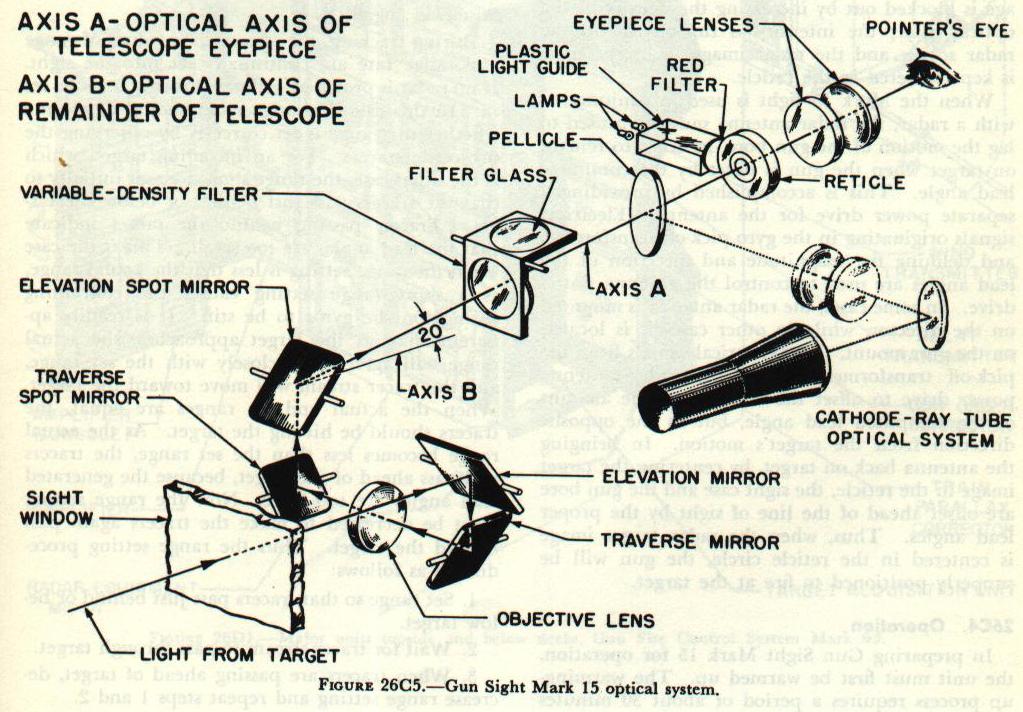
The optical system of Gun Sight Mark 15 includes a telescope, lead angle mirrors, spot mirrors, an optical filter, a reticle plate, and reticle illumination. In addition, some modifications include a cathode-ray tube and a pellicle for introducing its image into the line of sight. The arrangement of the optical system is shown in figure 26C5. The target image, after entering the sight case, is reflected from the elevation lead angle mirror to the traverse lead angle mirror, thence through the telescope objective lens to the deflection spot mirror. From here it is reflected to the elevation spot mirror, and then through the reticle plate to the telescope eyepiece assembly. When either of the gyros precesses, it actuates a linkage to offset the corresponding lead angle mirror, thus deflecting the target image. Since the position of the reticle is fixed, this means that the target image will no longer be centered in the reticle. The sight case must then be moved so as to bring the target image back into the reticle circle. The arrangement of the mirrors is such that the sight case must be offset ahead of the target in order to center the image. This causes the sight case axis to lead the target by the necessary amount of lead angle. In a similar manner, the introduction of spots deflects the target image and necessitates a change in the lead angle.
In those modifications of the sight which incorporate provisions for radar tracking, a cathode-ray tube is installed in the sight case. The radar image is reflected from a mirror to a pellicle in the optical axis of the telescope. This pellicle is a very thin plastic sheet which is semi-transparent, so that it reflects the radar image through the reticle plate to the telescope eyepiece, but still allows the optical target image to pass through for optical tracking. In radar tracking, the optical target image is blocked out by increasing the density of the optical filter; the intensity is turned up on the radar scope; and the radar image (a bright spot) is kept centered in the reticle.
When the Mark 15 sight is used in conjunction with a radar, the radar antenna must be caused to lag the motion of the gun bore, in order to remain on target when the gun is offset by the computed lead angle. This is accomplished by providing a separate power drive for the antenna. Electrical signals originating in the gyro pick-off transformers and defining the magnitude and direction of the lead angles are used to control the antenna power drive. In some cases, the radar antenna is mounted on the director, while in other cases it is located on the gun mount. The electrical signals from the pick-off transformers actuate the radar antenna power drive to offset the antenna by the amount of the computed lead angle, but in the opposite direction from the target’s motion. In bringing the antenna back on target, by centering the target image in the reticle, the sight case and the gun bore are offset ahead of the line of sight by the proper lead angles. Thus, when the radar target image is centered in the reticle circle, the gun will be properly positioned to fire at the target.
26C4. Operation
In preparing Gun Sight Mark 15 for operation, the unit must first be warmed up. The warming-up process requires a period of about 30 minutes for bringing the damping fluid to its operating temperature and viscosity. Bringing the gyros up to their designed operating speed requires about 6 minutes. When operating in an area where attack is likely, the sights are kept warmed up and ready for use.
Preliminary to firing, the target is located by means of a fixed auxiliary telescope mounted on top of the sight. The target is tracked briefly through the auxiliary telescope, after which the operator shifts to the gun-sight telescope. During this initial process the range is kept set at the minimum value in order to restrict movement of the gyro, or, if gyro cagers are installed, the gyros are kept caged. When the target image has been centered in the reticle circle, the cager is released and the proper range and range rate are set in. A similar process is used for radar tracking, except that in this case the auxiliary telescope cannot be used.
Tracking the target or radar spot is continued. The target or spot is kept centered in the reticle circle by smooth movement of the director. It is essential that all tracking movements be smooth, since sudden movements cause the generation of false lead angles.
During tracking, the appropriate values of range and range rate are continually set into the sight. If no radar is provided, estimated ranges must be set in. In this case the range setter should determine whether the range is set correctly by observing the projectile tracers. For an incoming target, which is the usual case, the range should be set initially so that the tracers pass just behind or below the target. Tracers passing behind the target indicate that the lead angles are too small. This is the case when the range setting is less than the actual range, as a short range setting causes the restraining springs on the gyros to be stiff. It is readily apparent that, as the target approaches, the actual range will agree more closely with the set range, and the tracer stream will move toward the target. When the actual and set ranges are equal, the tracers should be hitting the target. As the actual range becomes less than the set range, the tracers will pass ahead of the target, because the generated lead angles are too large. Now the range setting must be decreased to make the tracers again pass behind the target.
Thus the range setting procedure is as follows:
1. Set range so that tracers pass just behind or below target.
2. Wait for tracer stream to pass through target.
3. When tracers are passing ahead of target, decrease range setting and repeat steps one and two.
D. Gun Fire Control System Mark 63
26D1. General description
Gun Fire Control System Mark 63 is manually operated and is designed to control the fire of 40-mm and 3"/50 guns against air targets at ranges from 800 to 7,000 yards.
Range rate limits on later installations are plus 350 knots and minus 800 knots. Targets may be tracked either optically or by radar. The radar antenna is carried on the gun mount.
The system uses a disturbed line of sight, meaning that while the sight housing and gun barrels are aimed at future target position, the optical line of sight and radar beam remain on the present target position. See figure 26D2.

The major units included in the system are:
1. Gun sight Mark 15 or Mark 29.
2. Director pedestal.
3. Antenna mount.
4. Radar equipment.
5. Wind transmitter.
6. Target acquisition unit (TACU).
7. Train parallax corrector (if guns are displaced sufficiently far from the director to require parallax correction).
26D2. Operation
A crew of six is required for operation. Topside personnel are the control officer, the director pointer, the director range setter, and the gun control talker. The target acquisition unit (TACU) operator and the radar operator are stationed below decks.
A Lead-Computing Sight Mark 15 or Mark 29, employing air-driven gyroscopic computing mechanisms, is mounted on a pedestal-type director. The director is swung manually by the director pointer in train and elevation.
Tracking can be accomplished in two ways. If the target is visible, it is tracked by keeping the reflection of the target image centered on a fixed reticle in the optical telescope. This method is known as optical tracking. If the target is obscured, or in case of night firing, the director pointer tracks a radar target spot which is introduced into the optical line of sight by a train and elevation scope in the gun sight. This method is called blind tracking.
When the target is sighted optically, the director pointer slews the director to get on, using an auxiliary telescope. A caging switch on the left handle of the director is pressed during this operation to prevent the gyros from generating a large false lead angle. As quickly as possible after the target is picked up in the auxiliary telescope, the pointer shifts to the tracking telescope of the gun sight and starts tracking smoothly, releasing the caging switch as the target is tracked.
Corrective data from other units in the system (wind transmitter for wind corrections and radar for ranges and range rates) are transmitted to the director and applied as inputs to the gun sight automatically or by the range setter, who matches zero readers, thus sending these corrections into the gun sight. The corrections cause movement of the mirrors in the gun sight, changing the relative positions of the target image and reticle.
The pointer, in maintaining the center of the reticle on the target, causes the director and the guns it controls to be offset from the line of sight and to point ahead of (lead) the target, because of movement of the mirrors in the optical system caused by precession of the gyros. The lead angle compensates for the relative motion of the target and for the effects of gravity, wind, drift, and spots, if any.
The lead angle is composed of two components: one in elevation, the other in train. The latter is corrected for horizontal parallax before being used at the gun, in installations where this refinement is warranted. The amount the director is offset from the line of sight in elevation and train is continuously sent to the gun during tracking in the form of signals which control power drives at the gun.
26D3. Improved modifications
In later modifications of the Mark 63 system, the Mark 29 sight has replaced the Mark 15 sight, as it provides for handling greater target speeds. Also the Mark 1 Mod 0 director pedestal has replaced the Mark 51 director in later installations.
The Mark 1 Mod 0 director pedestal incorporates one important feature not installed on the Mark 51 director, a cross-roll gyro. When the computer “cross rolls” or swings about the line of sight because of deck inclination, the elevation and train gyros tend to exchange functions. This exchange, however, is retarded somewhat by gyro damping. To compensate for errors caused by the damping, the cross-roll gyro measures cross roll directly and modifies the output of the sight accordingly by means of cross-roll torque motors on the gyro output shafts in the Mark 29 sight.
26D4. Radar equipment
The earliest Mark 63 systems used Radar Equipment Mark 28, while all others use the Mark 34, which will be described. The Mark 34 radar sends to the gun sight values of range and range rate which are used in computing lead angles both in full and in partial radar control; in addition, the radar provides target-position signals for blind tracking. In blind tracking, as in optical tracking, the director is positioned manually, but the radar equipment aids the director pointer by locating an obscured target initially by means of the TACU unit, and providing a target indication in the sight as a spot in the scope which can then be tracked, once the radar beam has been placed on the target.
As shown in figures 26D1 and 26D3, the radar antenna is mounted in a gimbal above the gun trunnions on the mount.

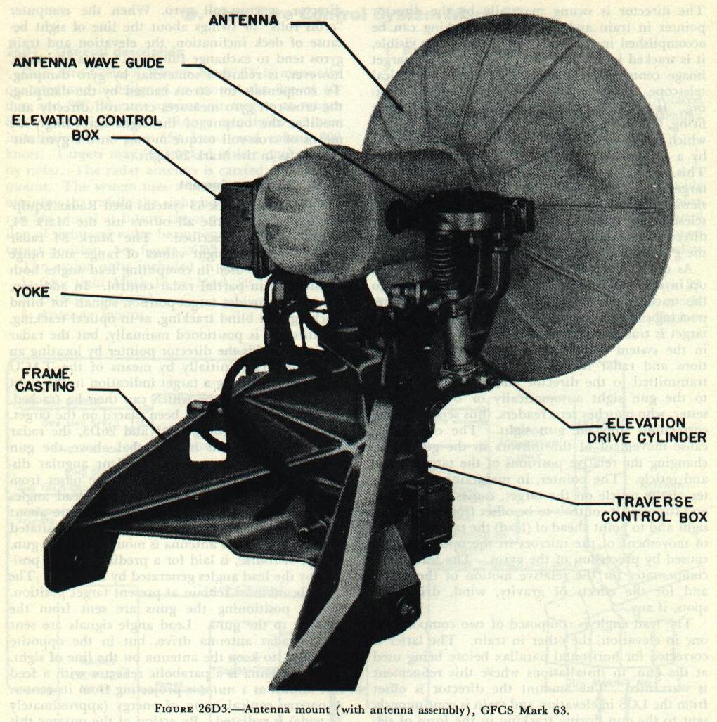
Sufficient angular displacement permits the antenna to be offset from the bore axis in accordance with the lead angles generated by the gun sight. The limits are about 30° in any direction. This feature is necessitated by the fact that the antenna is mounted on the gun, which, of course, is laid for a predicted target position by the lead angles generated by the sight.
The radar beam must remain at present target position. Signals positioning the guns are sent from the director to the guns. Lead angle signals are sent to the radar antenna drive, but in the opposite direction, to keep the antenna on the line of sight.
The antenna is a parabolic reflector with a feed line known as a nutator projecting from its center. A narrow conical beam of energy (approximately 3° wide) is radiated. By action of the nutator this beam is deflected 0.75° from the axis of the reflector and is rotated 30 cycles per second, thus providing a cone-shaped area of scan 4.5 degrees.
26D5. Target acquisition
The target acquisition unit (TACU), which is a part of the Mark 34 radar, is located in the radar room. When visibility is poor, or when numerous targets are at the same approximate location, the TACU aids the director operator in acquiring the designated target. The TACU operator receives target information from an outside station, such as a search radar or a lookout, and can control the position of the TACU spot in the director pointer’s train and elevation (T&E) scope to indicate the direction of movement necessary to point toward the designated target.
If the target fails to appear in the TACU scope, the TACU operator can cause the antenna to nod in elevation at an angle of either ±15° or ±5° by a selector switch. Search in bearing can also be accomplished by throwing a switch which causes the spot to move back and forth in the T&E-scope. If the director pointer follows the spot, the TACU operator is enabled to scan a small bearing sector about the designated bearing. Close cooperation between TACU operator and director pointer is necessary to locate and get on a designated target.
It should be noted that the spot used to coach the director pointer on the target is controlled by the TACU operator and is not the spot which appears on the pointer’s scope once the target lies within the radar beam. Once the target has been picked up by radar, the TACU operator can determine range, bearing, and elevation data from a scope of the TACU.
26D6. Ranging
The radar operator, also stationed in the radar room, has two units which provide visual information about the target; namely, the control indicator and the range unit. On the control indicator, echoes from targets within the radar beam appear as pips along the horizontal sweep. The range-measuring indication is a sharp drop or step in the sweep line. When the step is set adjacent to the leading edge of a pip, a counter on the range unit shows the range in yards. By throwing a selector switch, a choice of three sweeps is possible as shown in figure 26D4.

Main sweep, used for locating distant surface and air targets, shows all targets within the beam from 0 to 60,000 yards. The range crank moves the step to a maximum of 40,000 yards, beyond which target range must be estimated.
Expanded sweep is accurate and is sufficient for most air targets, since it includes the firing range. It shows all targets from 0 to 18,000 yards, the range step again moving as the range crank is turned.
Precision sweep, used for very accurate range measurement and tracking, covers any desired 2,500-yard sector of the entire measurable range (40,000 yards). In this case the step remains in the center of the sweep and the pips move along the trace as the crank is turned.
A small portion of the sweep (about 300 yards in range) is known as the range gate. The target is gated by turning the range crank on the range unit until the leading edge of the pip is adjacent to the sharp point at the base of the step. A drop in amplitude of all pips and grass along the sweep indicates that a target has been gated. Effective tracking can be accomplished only on gated targets, since no others will show up on the director pointer’s T&E-scope. Targets may be tracked (kept gated) either manually by moving the range crank or by an aided tracking unit which causes the range step to move along automatically at a uniform rate. For fast-moving targets, the latter will give smoother tracking.
26D7. Operation in train and elevation
The scope on the control unit duplicates the image on the director pointer’s T&E-scope. This train and elevation indicator permits the radar operator to work more closely with the director pointer.
The gun sight contains a T&E-scope for the information of the director pointer. Once the target is gated, the spot on the T&E-scope enables him to correct errors in the pointing, as shown in figure 26D5.

Since the radar beam is being rotated, the target which is gated but not exactly on the center of the antenna axis will return a signal of different strength for each position of the radar beam. Such a target will give an image (spot) displaced from the center of the T&E-scope, and the direction of the spot from the center indicates the direction in which the antenna must be moved to center the spot. When the target is exactly on the axis of the antenna, the spot is in the center of a circular reticle. Keeping the spot so centered tracks the target.
The T&E-scopes give indications of signal strength as well as pointing error. A strong echo appears as a bright spot, weaker echoes as small rings increasing in size as the echo becomes weaker. When the echo is no longer present, a concentric “no signal” circle settles inside the circular reticle at the center of the scope. The range accuracy of the Mark 34 radar is within 15 yards ±0.1 percent of the measured range, and the pointing accuracy is within 1 mil.
E. Gun Fire Control System Mark 56
26E1. General
Gun Fire Control System Mark 56, like other ordnance equipment, is constantly being improved. Thus the following discussion may not reflect current installations in every detail. General operating principles of Mark 56 systems are the same for all equipment; but the latest publications, instructions, and notices should be consulted.
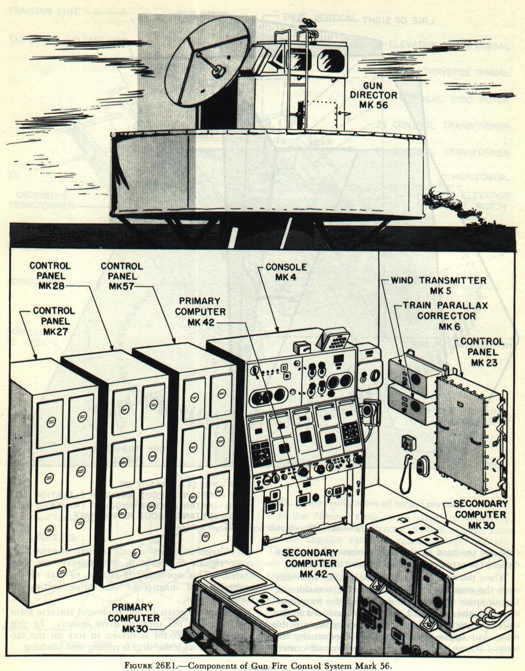
Gun Fire Control System Mark 56, illustrated in figure 26E1, is an intermediate-range antiaircraft fire control system. Designed for use against high-speed subsonic aircraft targets, it provides gun train, gun elevation, and fuze orders for 3-, 5- and 6-inch guns. It may also be used against surface targets. Where a ship has two batteries (of different calibers) capable of AA fire, the system can produce different gun orders for both batteries simultaneously, thus permitting both to fire on the same target. This variation is known as a dual-ballistic system.
The system incorporates:
1. Automatic radar tracking in bearing, elevation, and range, as accurate as the best optical tracking.
2. Remote control of the entire system from the control room below decks, which provides for rapid radar acquisition of obscured targets and for blind firing. Solution time of this system is relatively short (2 seconds), so firing can begin early in tracking.
The system consists essentially of a two-axis, power-driven, direct-line-of-sight director located above decks, and various computing units located in a control room below decks. Complete radar equipment is included as an integral part of the system. The radar antenna is mounted on the director, and all radar indicators are in the control room.
The system is operated by a crew of four men, including the control officer. The latter and the pointer are stationed in the director for optical acquisition and the tracking of visible targets, and the two other men are at a console in the control room. On the console are all radar indicators and operational controls for handling range and positioning the director. Acquisition of obscured targets is accomplished from the console by matching designating dials.
Director line of sight (including radar antenna) is stabilized by a gyro unit in the director. Computation of lead angles is based on director angular rates of motion in stabilized coordinates. The discussion to follow presents first a general treatment of the fire control problem as solved by the system, then a detailed description of system components and operational controls.

Figure 26E2 shows some of the space relations used in the Mark 56 system. The angular velocity of the line of sight can be resolved into angular rates in two planes, elevation and traverse, dE and dBs. In the GFCS Mark 56, these rates are measured by the rate gyro, which is stabilized and hence measures the rates in the true elevation and the true traverse plane.
The solution, however, requires the use of linear rates of target motion, in a plane perpendicular to the line of sight at the target’s position. This plane is called the cross-traverse plane, and contains RdE and RdBs. Since the target is not moving entirely in the cross-traverse plane, the range changes at the rate dR, measured along the line of sight. RdE, RdBs, and dR, then, are the three basic linear rates of target motion.
The first step in the solution of the problem by the Mark 56 is the determination of target position. Target bearing and elevation are measured by the director. As the target is tracked, director train, B′r′, and director elevation E′b are measured and transmitted by the synchros; electrical signals representing these angles are transmitted continuously to the computer. Target range (R) is measured by gating the target pip on the radar indicator. The range signal is transmitted automatically from the radar equipment to the computer.
Tracking the target is accomplished either optically or by radar. For optical tracking, a handgrip type of tracking control unit and a telescope are provided on the director. Rotation of the hand grips generates electrical signals that control the director power drives in elevation and train.
In automatic radar tracking, the tracking signals originate in the automatic tracking circuits of the radar equipment. These error signals vary with deviation of the target from the center of the radar beam when in conical scan. Automatic tracking is accurate within one-half mil.
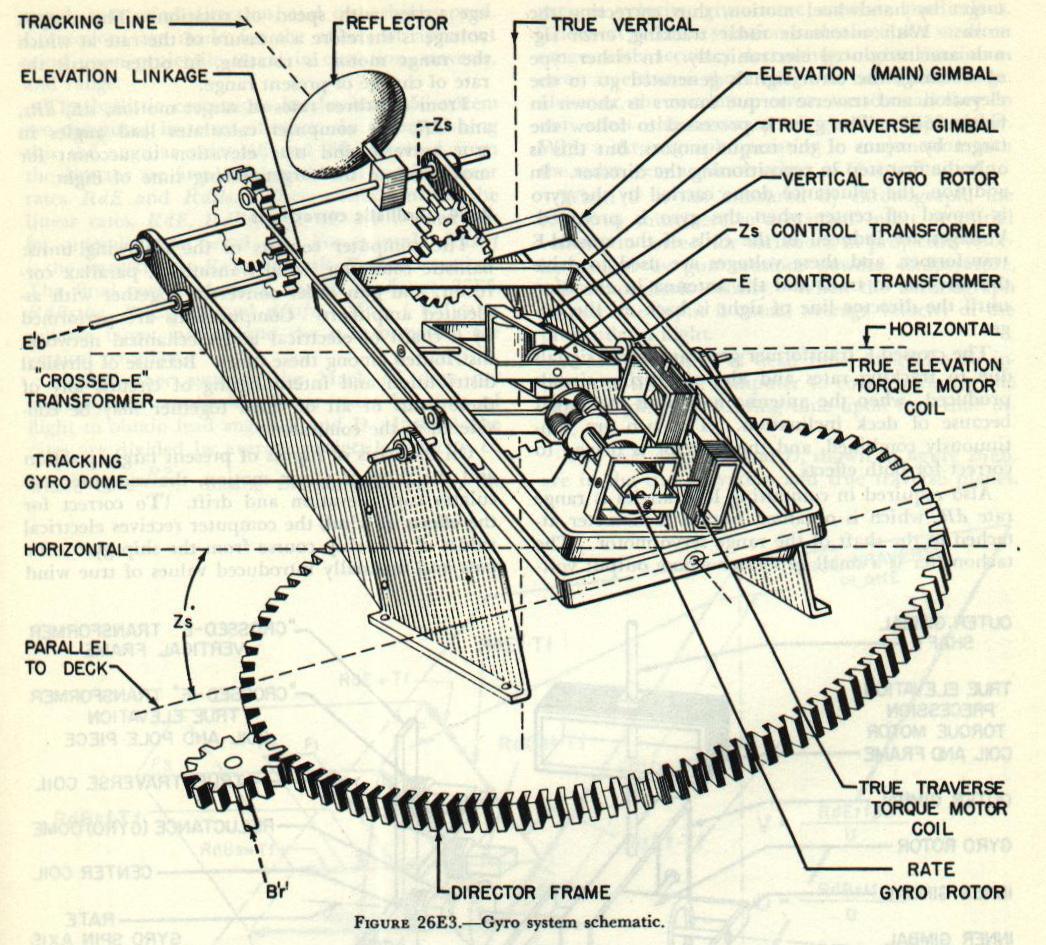
The director line of sight is stabilized by a gyro unit, located in a compartment at the rear of the director. The unit, shown schematically in figure 26E3, consists of a vertical gyro and a rate gyro. The gyroscope unit is mounted on pivots in the gyro compartment. The elevation linkage attached to the antenna elevating gear is used to tilt the gyro main (elevation) gimbal so as to maintain the gyro gimbal axes parallel to the line of sight.

The primary purpose of the vertical gyro is to establish a stable reference plane called the true traverse plane, as shown in figure 26E2. The vertical gyro, as shown in figure 26E4, also measures E, true elevation of the director line of sight above the horizontal, and Zs, cross-traverse angle. Like cross level, cross traverse is motion about the line of sight due to movement of the deck. However, cross traverse is measured in the cross-traverse plane, which is perpendicular to the line of sight, and therefore differs from cross level. The values of E and Zs are picked off by elevation and cross-traverse control transformers and are transmitted to the computer, where they are applied in calculating ballistic corrections and gun orders. Zs also goes to the cross-traverse drive gear of the rate gyro.
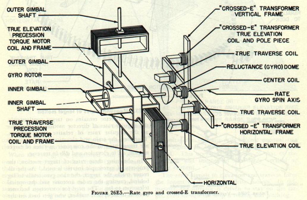
The rate gyro, shown in figure 26E5, controls the drive motors which position the director in train and elevation. The gyro does this by measuring the angular rates of target motion in the form of electrical tracking signals and combining these signals with the stabilizing signals generated as a result of deck motion. The algebraic sum of these signals is obtained in a set of pick-off coils called a crossed-E transformer and shown in figure 26E5. The crossed-E transformer is composed of five coils arranged to form a cross with axes at right angles. The center coil is energized by 100 volts, alternating current. This voltage induces voltages in the other coils. Supported by the vertical frame, coils are kept oriented in the vertical plane through the tracking line, as shown in figure 26E3, and are connected in phase opposition. The other two coils are oriented in the true traverse plane. Carried on the rate gyro shaft is the reluctance dome.
When the rate gyro is positioned with its center over the center coil of the crossed-E transformer, the air space between the dome and the transformer coils is the same, and the voltages induced in the coils on opposite sides of the transformer are the same, but opposite in phase. Consequently, the output is zero. When the dome moves off center, the voltages in opposite coils become unequal and error signals in elevation and traverse are generated. This operation is similar to that of the umbrella and magnet in the stable vertical or stable element.
The error signals in elevation and traverse form the inputs to the director drive motors. In this manner, the director is driven to stay on the target, even though the ship is rolling and pitching.
26E3. Measuring rates of target motion
If the director remains on target continuously, the angular rates of director motion are the same as the angular rates of relative target motion. Therefore, the train and elevation tracking signals are transmitted to the computer as rates of target motion, dE in elevation and dBs in traverse.
In obtaining these rates of target motion, the property of gyroscopic inertia is used. As the director tracks the target, the rate gyro tends to lag behind, causing the radar antenna and the optical telescopes to lag. The need for correction becomes obvious to an optical tracker, who gets back on the target by handwheel motion, thus correcting the error. With automatic radar tracking, error signals are introduced electronically. In either type of tracking, the error signals generated go to the elevation and traverse torque motors as shown in figure 26E5. The gyro is precessed to follow the target by means of the torque motors, but this is only the first step in repositioning the director. In addition, the reluctance dome carried by the gyro is moved off center when the gyro is precessed. Voltages are induced in the coils of the crossed-E transformer, and these voltages are used to drive the director in train and the antenna in elevation until the director line of sight is back on the target.
The crossed-E transformer generates error signals due to tracking rates and also stabilizing signals produced when the antenna moves off the target because of deck inclination. The two are continuously combined, and the director is driven to correct for both effects.
Also required in computing lead angles is range rate dR, which is obtained from a tachometer attached to the shaft of the range rate servo motor. The tachometer is a small generator whose output voltage varies with speed of rotation. The output voltage is therefore a measure of the rate at which the range motor is rotating, in other words the rate of change of present range.
From the three rates of target motion, dE, dBs, and dR, the computer calculates lead angles in true traverse and true elevation to account for movement of the target during time of flight.
26E4. Ballistic corrections
The computer consists of the following units: ballistic computer, wind transmitter, parallax corrector, and gun order converter, together with associated amplifiers. Computations are performed by a chain of electrical and mechanical networks distributed among these units. Because of physical distribution and intermingling of circuits, any of these units or all of them together may be considered as the computer.
On the basis of inputs of present target position and the rates of target motion, the computer calculates superelevation and drift. To correct for the effects of wind, the computer receives electrical values of own-ship course from the ship gyro compass and manually introduced values of true wind speed, true wind direction, and own ship’s speed. Corrections are made for the effects of apparent wind upon projectile travel in elevation, traverse, and range.
The ballistic corrections in the Mark 56 system are computed in terms of rates. In accomplishing this, the angular rates dE and dBs received from the director are first multiplied by R to give linear rates RdE and RdBs. Then corrections to the linear rates, RdE, RdBs, and dR, are worked out for superelevation, wind, etc. For example, RdBsf is the correction to RdBs for drift, RdBsw for wind. The final corrected rates, shown in figure 26E6, are RdBstfw, RdEtfpw, and dRtfw. The t indicates relative target motion and the p a correction for vertical parallax.
Unlike other systems, the Mark 56 does not multiply the applicable linear rates by time of flight to obtain lead angles V and D. Instead, the rates are divided by average projectile velocity U, where U = R2/Tf. Basing the solution on U, the average velocity, gives more accurate predictions. The most accurate solution is obtained at a medium range, with accuracy decreasing to give maximum error at either a short range or maximum range. However, the maximum errors are so small they do not affect the accuracy of gunfire appreciably. With a chronograph operating in conjunction with the radar, very accurate values of U are obtained.
When U is not measured by chronograph, the computer must receive a manual input of initial velocity to correct for variations in projectile velocity caused by gun erosion, powder temperature, and atmospheric density. When the chronograph is used, the input is actual average velocity of the projectile in flight.
A manual input of dead time must also be introduced into the computer to compensate for the effect of gun-crew loading time upon fuze time order.

The lead angles V and D, shown in figure 26E6, are in the true elevation and true traverse planes.
Since present target position is measured in deck coordinates, the lead angles must be converted into their equivalent angles in deck coordinates. This conversion is performed in the Mark 30 computer by a graphic device called the axis converter. The converter is a small dummy-gun arrangement which reproduces the actual conditions of the problem. The stabilized lead angles are set into the converter, and the correct values of lead angles in deck coordinates are continuously picked off and used in making up gun orders.
Parallax correction is accomplished in three parts: (1) an elevation correction to account for the vertical displacement of the gun mount from the director, (2) a correction to director train to correct for the fore-and-aft displacement of the director from the ship’s reference point, (3) unit parallax correction (100-yard base length), which is transmitted to the gun mount, where a correction is made to gun order for displacement of gun mount from reference point.
26E5. Composition of gun orders
With the lead angles V and D in true coordinates converted to the deck-plane coordinates as V′d and D′d, they can be added to E′b and B′r′. The gun elevation order and gun train order are formed as follows:
B′gr = B′r′ + D′d
These values are transmitted to the gun, where a final correction for horizontal gun parallax is introduced into gun train order.
The fuze setting order (F) for mechanical time fuzes is computed in the Mark 42 computer.
26E6. Summary of system operation
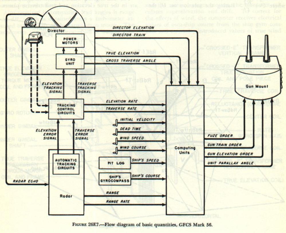
Figure 26E7 shows the flow of basic quantities in the system when using automatic radar tracking, which is the usual method of operation. The radar equipment in the radar room receives target echoes from the antenna and transmits traverse and elevation error signals to the gyro unit as tracking signals and to the computer as rates of target motion. By resetting the control switches, signals from the optical tracking control unit in the director may be selected in place of radar error signals. The radar equipment transmits range and range rate to the computer during both radar and optical tracking.
In the gyro unit, tracking signals are added to stabilizing signals. The resultant signals control the director power drives. As the director tracks the target, director position is measured by synchros, and director train and elevation are transmitted to the computer. The gyro unit also transmits values of true director elevation and cross-traverse angle to the computer.
Own-ship course and speed are introduced to the computer electrically from the gyro compass and pitometer log, while true wind speed and direction, initial velocity, and dead time are introduced manually. The computer calculates lead angles and ballistic corrections, and makes up and transmits gun elevation order, gun train order, fuze time order, and unit parallax correction to the guns. Within two seconds of the start of steady tracking (either optical or radar), the computer is producing accurate gun orders.
26E7. System components
The components of a single-ballistic system of GFCS Mark 56, figures 26E1 and 26E7, are:
1. Gun Director Mark 56.
2. Radar Equipment Mark 35.
3. Console Mark 4.
4. Computer Mark 42 (ballistic computer).
5. Computer Mark 30 (gun-order converter).
6. Wind Transmitter Mark 5.
7. Train Parallax Corrector Mark 6.
8. Chronograph.
9. Bearing Indicator Mark 10.
10. Selector Switch Mark 13.
11. Control Panel Mark 23.
12. Control Panels Mark 27 and Mark 28.
13. Train and elevation amplidyne generators.
14. Motor-generator set.
In addition to these units, a dual-ballistic system requires for computing gun orders for the secondary ballistics:
15. Computer Mark 42.
16. Computer Mark 30.
17. Control Panel Mark 57.
18. Ballistic selector switch.
19. Secondary ballistics fuze control unit.
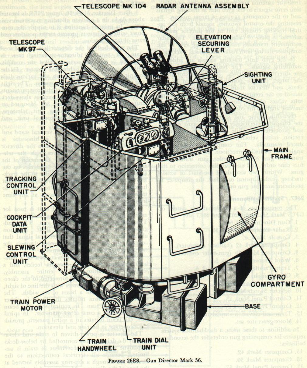
1. Gun Director Mark 56, figure 26E8, is located above decks, in a position affording maximum visibility. Its primary function is to supply the computer with continuous present target position and rates of target motion.
The main body of the director is a shell of steel plate. A two-man director-operating crew is stationed in the left section, called the cockpit, with the control officer behind the pointer. In the cockpit are the tracking controls and various dials and switches used to operate the system. The right section consists of four watertight compartments which house the gyro unit and various above-deck units of Radar Equipment Mark 35. Mounted on the main body are the sighting unit, telescope, tracking control unit, slewing control unit, and radar antenna.
The sighting unit consists of a vertical stand and elevating crossarm on which a binocular is mounted. The crossarm is geared to the director elevation transmitters and moves with the telescope line of sight in elevation. Operation of the sighting unit is controlled by the handgrips on the slewing control unit, which is similar to the tracking control unit. A trigger-type switch in the right handgrip of this unit allows the control officer to take slewing control of the director at any time from any other mode of control.
The pointer’s tracking control unit is used for moving the director when tracking visible targets. This unit rotates about a vertical axis. The hand-grips rotate about a horizontal shaft. Rotation about either axis generates an electrical signal that controls the director power motors through the rate gyro and crossed-E transformer.
The radar antenna assembly consists of a parabolic reflector, a nutating antenna feeder, and a scanning mechanism. The entire assembly, mounted on trunnions and connected to the director elevation gearing, elevates with the line of sight.
The antenna forms a beam of set width. The scanning mechanism nutates the beam in either conical or spiral scan. In conical scan, the beam nutates through a cone of set diameter. In spiral scan, the beam nutates in a spiral pattern, providing a coverage in bearing and elevation.
The director is power-driven in train and elevation by d-c drive motors controlled by below-decks amplidyne generators. Movement in train is unlimited, because all electrical connections to the director are through a slip-ring assembly located at the base of the director. Movement of the director in elevation is limited by mechanical stops. Electrical limit switches cut out power to the drive motors before the mechanical limit stops are reached.
The director is provided with locks for securing in train and elevation when the director is not in use. Securing locks incorporate a protective micro switch that cuts out power to the amplidyne generators when either lock is in the secured position.
A train handwheel and an elevation handknob are provided so that the director may be moved for securing purposes when the power motors are off. For transmitting values of train and elevation, the director is provided with synchro transmitters connected to the train and elevation drive-gear systems.
2. Radar Equipment Mark 35 supplies: (a) the computing units with continuous values of target range and range rates for both optical and radar tracking; and (b) the director with signal for tracking obscured targets. Once on target, the system will track automatically when radar control is being used. Components of Radar Equipment Mark 35 located above decks are the antenna, scanning mechanism and motor, transmitter, and receiver. The radar indicators, range controls, adjustment controls, and automatic tracking circuits are located below decks on Console Mark 4.
3. Console Mark 4, figure 26E1, is the below-decks operational center. On it are the knobs, dials, and indicators necessary for below-decks operation of the system. While various phases of the computations are performed in separate computing units, inputs and power to these units are controlled from the console.
The console consists of four main sections: a dial section at the top, the radar section, the operational section, and Computer Mark 42 at the bottom. Bearing Indicator Mark 10 is mounted on the right side of the console.
On the face of the dial sections are knobs and dials for hand inputs to computing units; dials indicating range, elevation, and bearing; tracking-control indicating lamps; and a switch controlling computer operation.
The radar section consists of five panels containing the A/R-indicator, E-indicator, and B-indicator and switches for controlling radar operation.
The operational section contains the handknobs, slew levers, and switches for controlling the director in train and elevation, and for controlling range, antenna scan, and modes of operation.
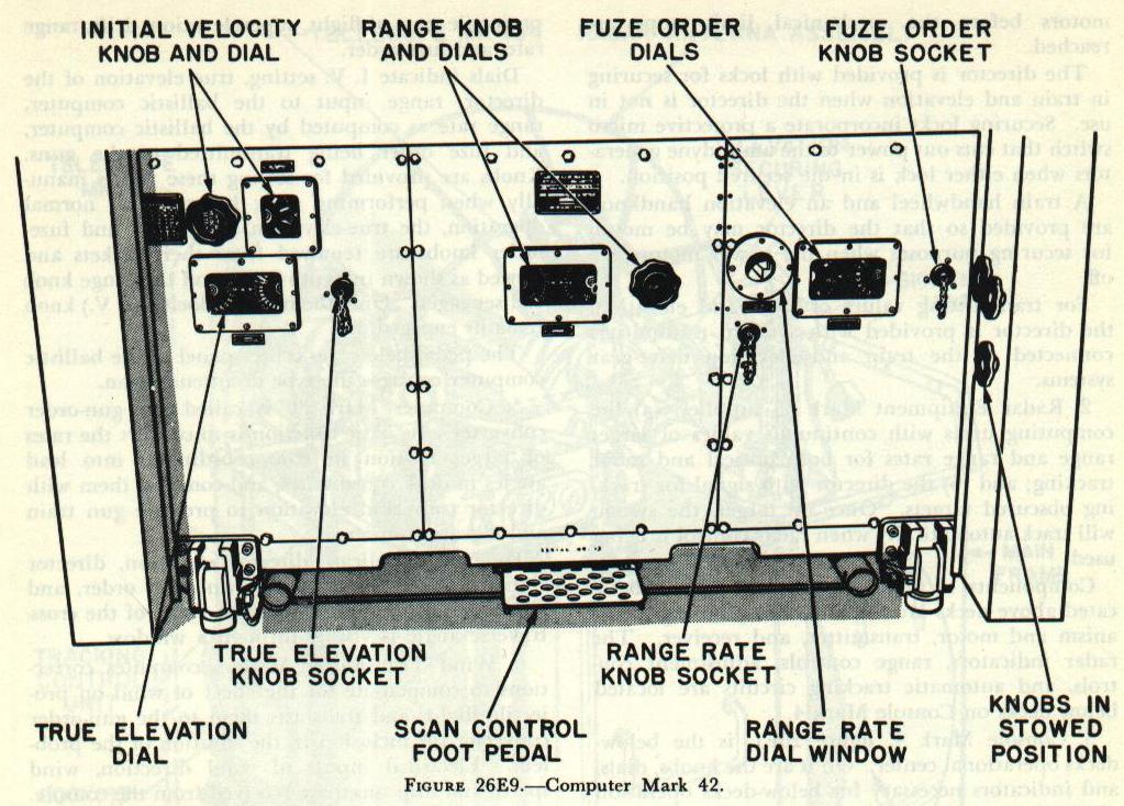
4. Computer Mark 42, figure 26E9, is the ballistics computer. Its primary function is to compute projectile time of flight, superelevation, drift, range rate, and fuze order. Dials indicate I.V. setting, true elevation of the director, range input to the ballistic computer, range rate as computed by the ballistic computer, and fuze order being transmitted to the guns. Knobs are provided for setting these values manually when performing tests; however, for normal operation, the true-elevation, range-rate, and fuze-order knobs are removed from their sockets and stowed as shown in figure 26E9, and the range knob is disengaged. Only the initial velocity (I.V.) knob remains engaged. The pedal below the center panel of the ballistic computer controls the type of antenna scan.
5. Computer Mark 30 is called the gun-order converter. Its basic function is to convert the rates of target motion in true coordinates into lead angles in deck coordinates, and combine them with director train and elevation to produce gun train and elevation orders. Four dials indicate director elevation, director train corrected for parallax, gun train order, and gun elevation order. The input value of the cross-traverse angle is visible through a window.
6. Wind Transmitter Mark 5 computes corrections to compensate for the effect of wind on projectile flight, and transmits them to the gun-order converter for inclusion in the solution of the problem. Electrical inputs of wind direction, wind speed, and ship speed are received from the console. A dial on the face of the wind transmitter indicates the direction from which apparent wind is blowing.
7. Train Parallax Corrector Mark 6 computes a correction for the displacement of the gun mount from the director along the ship’s fore-and-aft axis. It receives values of range, elevation, and director train. The outputs are: (a) director train corrected to the ship reference point, which is transmitted to the gun-order converter; (b) unit parallax correction, which is transmitted to the gun for correcting the value of gun train order. A dial indicates the unit parallax correction.
8. The chronograph measures the average velocity of the projectile, so that I.V. may be determined accurately.
9. Bearing Indicator Mark 10 indicates director bearing (both relative and true) to the below-decks operating crew.
10. Selector Switch Mark 13, also called the Computer Mark 1A switch, is installed only on ships where GFCS Mark 56 is to be connected with Computer Mark 1A for surface fire. In the Computer Mark 1A position, the switch allows values of director train and range to be transmitted to Computer Mark 1A.
26E9. Dual-ballistics units
A dual-ballistic system tracks one target but computes two sets of gun orders for guns of different ballistics. For example, in a typical light-cruiser installation, GFCS Mark 56 computes gun orders for 3"/50 and 6"/47 guns.
The dual-ballistics system requires a second Computer Mark 42 for the secondary ballistics, using the same inputs as the primary ballistics computer, and a Computer Mark 30 which computes gun train order and gun elevation order for the secondary ballistics.
The ballistic selector switch controls power to the secondary ballistics-computing units. It has two positions: PRIMARY and BOTH. The secondary units are energized when this switch is in BOTH.
26E10. Control Officer’s Station
The control officer has available the following operational controls:
1. Telephone-selector switch. This switch has three positions: AIR DEFENSE, LOCAL, and BOTH. The air defense circuit is used primarily for target designation; outlets are provided for the control officer, radar operator, target designation station, air defense station, and the other directors. The local circuit is used primarily for gun control; its outlets include the control officer, director operator, radar tracker, mount captain, and gun crew. When the switch is turned to BOTH, the two circuits are connected in parallel. But because of the number of outlets on these lines, the circuits are paralleled only for training and testing.
2. Slewing control unit, sighting unit, and slew switch. The control officer can slew the director in train and elevation at any time by pressing his slew switch. This will take control away from any other mode of tracking. The control officer slews the director by rotating the handgrips of the slewing control unit for elevation control and by rotating the head of this unit for train control. The target is followed by use of the binocular mounted on the sighting unit. The binocular is kept parallel to the line of sight by an elevation input to the crossarm. The left handgrip of the slewing control unit has a press-to-talk switch which is equivalent to the mouthpiece button of the sound-powered telephone.
3. Radar-optical switch. This switch selects the type of tracking when the slew switch is released. If the radar-optical switch is positioned on RADAR, the radar console controls the director power drives. When this switch is set on OPTICAL, the tracking control unit has control. Two small lights indicate the station in control. When the slew switch is closed, the control officer can still give control to one of the other stations by closing a precedence button on his handgrip. This causes a take-over buzzer to sound in either station, depending on the position of the radar-optical switch. The station at which the buzzer sounds can bypass the slew control by closing a take-over switch, a button on the handgrip of the tracking control unit, and the scan control foot switch at the console. This feature enables the control officer to relinquish control to another station while still slewing the director. To regain slewing control, he must release the slew switch, thus disengaging the precedence switch, and then close the slew switch again.
4. Cockpit data unit. This unit contains the telephone selector switch, target designation lamp, radar range dial, director train and elevation dials, and radar-optical switch.
5. Hand microphone. This is used by the control officer to give orders to the gun crews.
6. Cease-firing contact maker. This is for communicating CEASE FIRING order to the gun crew.
26E11. Director Operator’s Station
1. Telescope Mark 97. The director operator tracks a visible target by keeping the crosshairs of the telescope reticle on the target.
2. Tracking control unit. This unit is operative when the radar-optical switch is on OPTICAL and the slew switch is open; or when the slew switch is closed, precedence switch is closed, radar-optical switch is on OPTICAL, and director operator’s take-over switch is closed.
Since tracking signals are used in the computer as the rates of target motion, smooth tracking is of primary importance to the computation of accurate gun orders. To help the director operator track smoothly, the tracking signals from the tracking control unit are fed through an aided tracking circuit. For an instant after the tracking rates are changed, the director moves at higher rates than called for by the target’s motion. The result is that the line of sight hops closer to the target and then settles down to the new rates.
A firing key with a safety lock is inset in the right-hand grip of the tracking control unit. To close the firing key, the director operator must first release this safety lock by pressing the lever to the left.
3. The press-to-talk switch is located on the left handgrip of the tracking control unit. It is the equivalent of a mouthpiece button on the sound-powered phones.
4. The amplidyne power switch controls power to the amplidyne generators which supply the director drive motors. The amplidynes will not start before the gyro READY lamp lights, or the securing locks are off.
5. The cockpit illumination switch controls dial illumination to the cockpit dial unit and telescope reticle lamp.
26E12. Radar Operator’s Station

The radar operator has available the following operational controls (fig. 26E10):
1. Radar indicators. Two oscilloscopes, the A/R-scope and the E-scope, provide the radar operator with his “view” of the target.
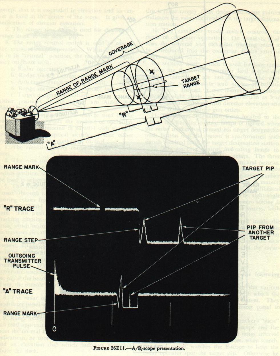
The A/R-scope, figures 26E10 and 26E11, has a double-trace presentation. The lower trace (A-sweep) extends from 0 yards. The range mark is movable and can be set on the target pip. Scribe marks on the scope face indicate the graduations in yards. The upper trace (R-sweep) is the expansion of the A-sweep, 500 yards either side of the range mark. The range step remains fixed near the center of the R-sweep and coincides with the range mark. Echoes from stationary targets and the 1,000-yard markers (only one of which is visible at any time) move past the range step as the target pip is moved along the A-sweep.

The E-scope, figure 26E12, shows range (horizontally) in yards, and director true elevation (vertically) in degrees. The vertical width of the trace depends on the type of antenna scan. The range mark is a bright vertical line extending from top to bottom of the sweep. Target echoes are vertical lines in elevation. Two curved lines on the scope face furnish an indication of target altitude.
Although normal E-presentation is generally used, an expanded presentation is available by turning the elevation sweep switch to EXPANDED. Expanded sweep shows the same trace as normal, except that it is expanded in elevation and its center is fixed at the center of the scope. It gives no indication of director elevation.
2. The range slew lever is used for slewing the range mark to the target pip.
3. The range control switch is used to control the mode of range operation. When this switch is in its “normal” position, the range input signal may originate with:
a. Radar operator’s range slew lever.
b. Radar tracker’s range crank.
c. Automatic range-tracking circuit.
d. Range memory circuit (“coast” button).
e. Target designation station.
Other positions of this switch are AIDED AA, AIDED SURFACE, and CALIBRATE.
4. The radar-optical switch may be used by the radar operator to select the method of operation. This switch is connected in parallel with the control officer’s radar-optical switch, so that either station may select the method of control.
5. The elevation crank controls director elevation.
6. The scan control switch, which controls the type of antenna scan, is usually placed on the foot-switch position, so that the scan control pedal can be used to select the type of scan.
7. The coast push button allows the system to “coast” through radar interference such as: (a) obscuring echoes from objects close to the target; or (b) radar “blind spots” caused by own-ship structure. This push button cuts out the automatic tracking circuits and substitutes the memory circuits, which maintain the existing rates of motion in traverse, elevation, and range. The system will coast at these rates for as long as the button is pressed, up to a maximum time of about two minutes. However, the button should be pressed only long enough for the target pip to clear the interference. When the button is released, the automatic tracking circuits will lock back on target pip if the beam is sufficiently close to the target; if not, the console operators must get back on target manually.
8. The radar controls are the knobs on the demodulator panel which control the operation of the radar equipment.
9. Range and elevation dials. The radar operator can read approximate director elevation and range from the normal E-scope presentation. For precise indications, he uses a fine and a coarse range dial, and an elevation dial which indicates elevation above the deck. The range dials indicate the value of range being introduced into the computer (normally this is radar range). The designated range pointer indicates the value received from the target designation station.
10. The computer mode switch controls the mode of computer operation. On NORMAL, it allows the traverse and elevation tracking rates to be introduced into the computer as the rates of target motion. On MANUAL INPUT, which is used for long-range surface fire (in which computer lead angles and ballistic corrections are not accurate), the computer does not calculate lead angles or ballistic corrections. Instead, it uses manually introduced values of sight angle and sight deflection as lead angles, combining them with director elevation and director train to produce gun orders.
11. The target-designation lamp located to the left of the tracking control lamps is lighted when the radar tracker has pressed his target designation push button and the system is synchronized with signals received from the target designation station.
12. The tracking control indicating lamps indicate the setting of the tracking relays. The three lights are labeled RADAR, SLEW switch, and OPTICAL.
13. The sight-angle and sight-deflection knobs and counters are used during long-range surface firing when the computer is operating in manual input. The sight-deflection counter is calibrated in mils; its zero setting is 500. The sight-angle counter is calibrated in minutes; its zero setting is 2,000. For normal operation of the system, both counters are set to their zero settings.
14. The take-over buzzer is located inside the console and indicates that the control officer wants the console operators to take over control for radar tracking. This buzzer sounds when both the slew and precedence switches are closed and the radar-optical switch is on RADAR.
26E13. Radar tracker’s station
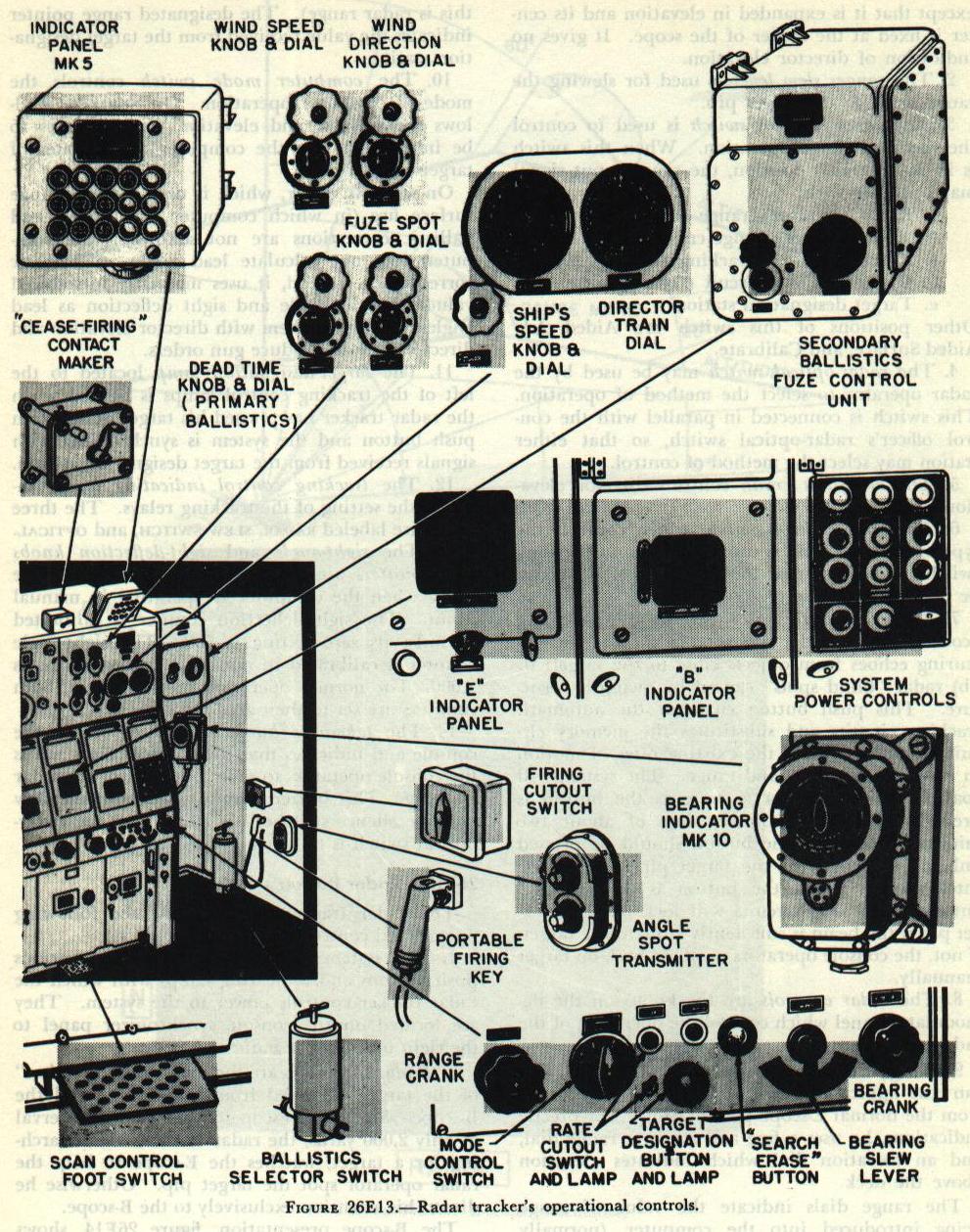
The radar tracker has available the following operational controls, figure 26E13:
1. The system power controls are the various push buttons and indicating lamps with which the radar tracker controls power to the system. They are located on the console synchronizer panel to the right of the radar indicators.
2. Radar indicators are the radar tracker’s “view” of the target, obtained from the E-scope and the B-scope. Since the B-scope covers a range interval of only 2,000 yards, the radar tracker, when searching for a target, watches the E-scope to help the radar operator spot the target pip. Otherwise he directs his attention exclusively to the B-scope.
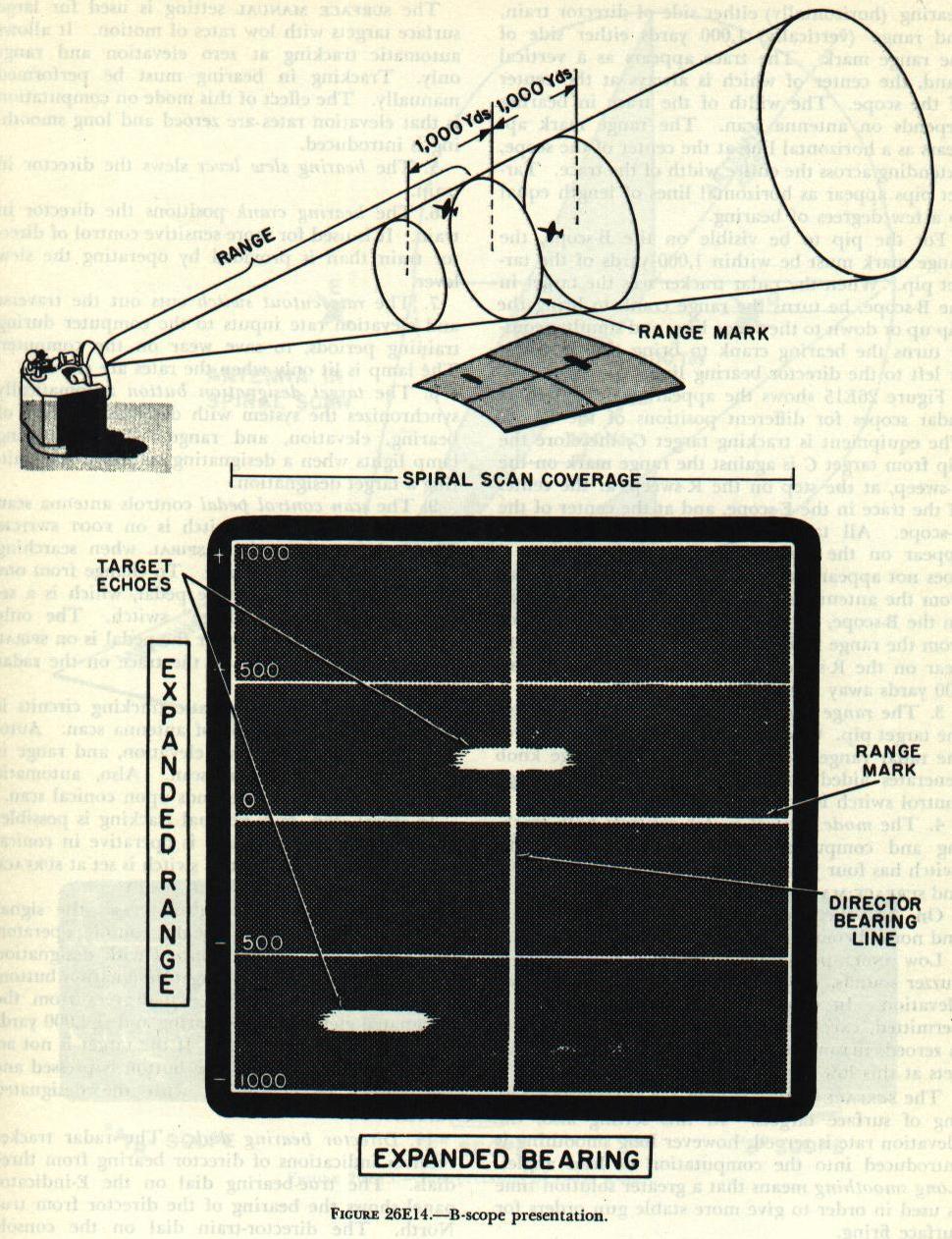
The B-scope presentation, figure 26E14, shows bearing (horizontally) either side of director train, and range (vertically) 1,000 yards either side of the range mark. The trace appears as a vertical band, the center of which is always at the center of the scope. The width of the trace in bearing depends on antenna scan. The range mark appears as a horizontal line at the center of the scope, extending across the entire width of the trace. Target pips appear as horizontal lines of length equal to a few degrees of bearing.
For the pip to be visible on the B-scope, the range mark must be within 1,000 yards of the target pip. When the radar tracker sees the target in the B-scope, he turns the range crank to bring the pip up or down to the range line, and simultaneously turns the bearing crank to bring the pip right or left to the director bearing line.
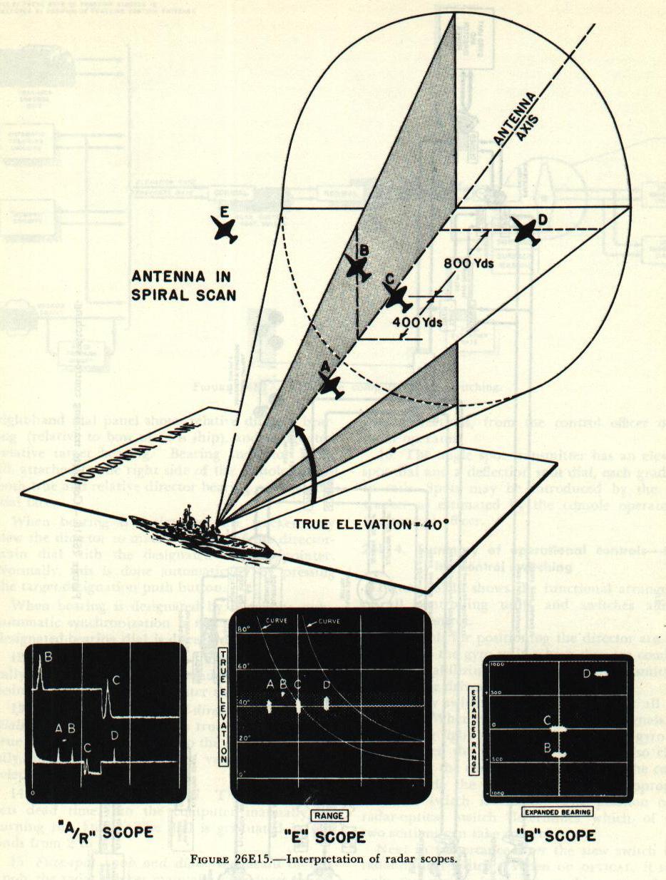
Figure 26E15 shows the appearance of all three radar scopes for different positions of the target. The equipment is tracking target C; therefore the pip from target C is against the range mark on the A-sweep, at the step on the R-sweep, at the center of the trace in the E-scope, and at the center of the B-scope. All targets covered by the spiral scan appear on the A-sweep and E-scope. Target F does not appear on any scope, because it is too far from the antenna axis. Target A does not appear on the B-scope, because it is more than 1,000 yards from the range mark. Targets A and D do not appear on the R-sweep, because they are more than 500 yards away from the range mark.
3. The range crank positions the range mark on the target pip. One revolution of the knob changes the radar range by 2,000 yards. The range knob generates aided tracking signals when the range control switch is at AIDED AA or AIDED SURFACE.
4. The mode control switch controls both tracking and computing modes of operation. This switch has four positions: AA, LOW ANGLE, SURFACE, and SURFACE MANUAL.
On AA, the usual setting, automatic tracking and normal computing are allowed.
LOW ANGLE position is used when the low angle buzzer sounds, indicating a target below 1 degree elevation. In this setting, automatic tracking is permitted, except that the elevation tracking rate is zeroed, inasmuch as this signal is erratic for targets at this low angle.
The SURFACE setting is used for automatic tracking of surface targets. In this setting also, the elevation rate is zeroed; however, long smoothing is introduced into the computation of lead angles. Long smoothing means that a greater solution time is used in order to give more stable gun orders for surface firing.
The SURFACE MANUAL setting is used for large surface targets with low rates of motion. It allows automatic tracking at zero elevation and range only. Tracking in bearing must be performed manually. The effect of this mode on computation is that elevation rates are zeroed and long smoothing is introduced.
5. The bearing slew lever slews the director in train.
6. The bearing crank positions the director in train. It is used for more sensitive control of director train than is provided by operating the slew lever.
7. The rate cutout switch cuts out the traverse and elevation rate inputs to the computer during training periods, to save wear on the computer. The lamp is lit only when the rates are cut out.
8. The target designation button automatically synchronizes the system with designated values of bearing, elevation, and range. The indicating lamp lights when a designating station is transmitting a target designation.
9. The scan control pedal controls antenna scan when the scan control switch is on FOOT SWITCH. The radar tracker selects SPIRAL when searching and CONICAL when tracking. To change from one to the other, he presses the pedal, which is a sequence-type “press-to-change” switch. The only visible indication of whether the pedal is on SPIRAL or CONICAL is the width of the trace on the radar indicators.
Operation of the automatic tracking circuits is interlocked with the type of antenna scan. Automatic tracking in bearing, elevation, and range is possible only in conical scan. Also, automatic gain control normally depends upon conical scan. In spiral scan, only manual tracking is possible; however, the bearing crank is operative in conical scan when the mode control switch is set at SURFACE MANUAL.
10. The search erase button erases the signal superimposed manually by the console operators when the system is synchronized with designation data. After pressing the target designation button, the operators can search ±20 degrees from the designated elevation and bearing and ±4,000 yards from the designated range. If the target is not acquired then, the search erase button is pressed and the system resynchronizes with the designated values.
11. Director bearing dials. The radar tracker receives indications of director bearing from three dials. The true-bearing dial on the E-indicator panel shows the bearing of the director from true North. The director-train dial on the console right-hand dial panel shows relative director bearing (relative to bow of own ship), and designated relative target bearing. Bearing Indicator Mark 10, attached to the right side of the console, shows both true and relative director bearing on the same dial face.
When bearing is designated, the tracker may slew the director to match the zero of the director train dial with the designated bearing pointer. Normally, this is done automatically by pressing the target-designation push button. When bearing is designated by telephone only, automatic synchronization is not possible and the designated-bearing dial is disregarded.
12. Ship speed is normally introduced automatically, but can be set in manually by matching pointers on the inner and outer ship-speed dials.
13. Wind-speed and wind-direction knobs and dials. The radar tracker sets true wind speed and true bearing of true wind into the computer manually, in accordance with the values received by telephone.
14. Dead-time knob and dial. The radar tracker sets dead time into the computer manually by turning this knob. The dial is graduated in seconds from 2 to 6.
15. Fuze-spot knob and dial. By means of this knob, the radar tracker manually introduces range-spot corrections, from the control officer or the radar operator.
16. The angle spot transmitter has an elevation spot dial and a deflection spot dial, each graduated in mils. Spots may be introduced by the radar tracker as estimated by the console operators or the control officer.
26E14. Summary of operational controls — tracking control switching
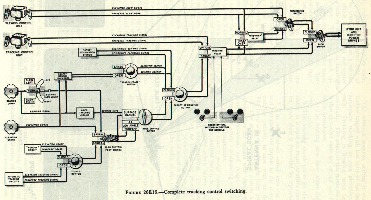
Figure 26E16 shows the functional arrangement of all controlling units and switches affecting tracking control. All signals for positioning the director are introduced into the gyro unit, where they are combined with the stabilizing signals and then transmitted to the director drives.
The slew switch takes precedence over all other switches. When closed, it allows only signals from the slewing sight to be introduced to the gyro unit, except when the precedence switch is also closed; then either the tracking control unit or the console can override the slew signals, if the appropriate take-over switch is closed. The position of the radar-optical switch determines which of these two stations can take control.
Next in importance after the slew switch is the radar-optical switch. When on OPTICAL, it selects only the signals from the tracking control unit; when on RADAR, it allows signals from the console to take over.
The target-designation push button takes precedence over all other console controls. When closed, it selects the designating signals from the target designating station. Signals from the bearing and elevation cranks on the console may be introduced to search within ±20 degrees of designated values.
When the mode control switch is set at SURFACE MANUAL, the bearing crank on the console has control of director bearing. Either manual or automatic tracking in elevation is possible, depending on the type of scan control in use. The other three positions of the mode control switch allow full automatic tracking, depending on scan control.
The scan control foot switch serves the function of choosing between manual and automatic tracking. With the scan control in SPIRAL, only manual tracking (with the bearing crank, slew lever, and elevation crank) is possible. The bearing crank signal goes through only if the bearing slew lever is set at NORMAL.
Automatic tracking is possible only in conical scan. The memory circuits are substituted for the automatic tracking circuits when the coast push button is pressed. The automatic tracking circuits will control the director if: (1) the coast push button is on OPEN; (2) the scan control pedal is on CONICAL; (3) the mode control switch is set at AA, SURFACE, or LOW ANGLE; (4) the target-designation push button is on OPEN; (5) the tracking switch is in RADAR; and (6) the slew switch is OPEN, or, if closed, when the precedence switch is also closed so as to activate the TAKE-OVER mode of the take-over relay. The scan control foot switch serves as the take-over switch for radar tracking, actuating the TAKE-OVER mode in conical scan.
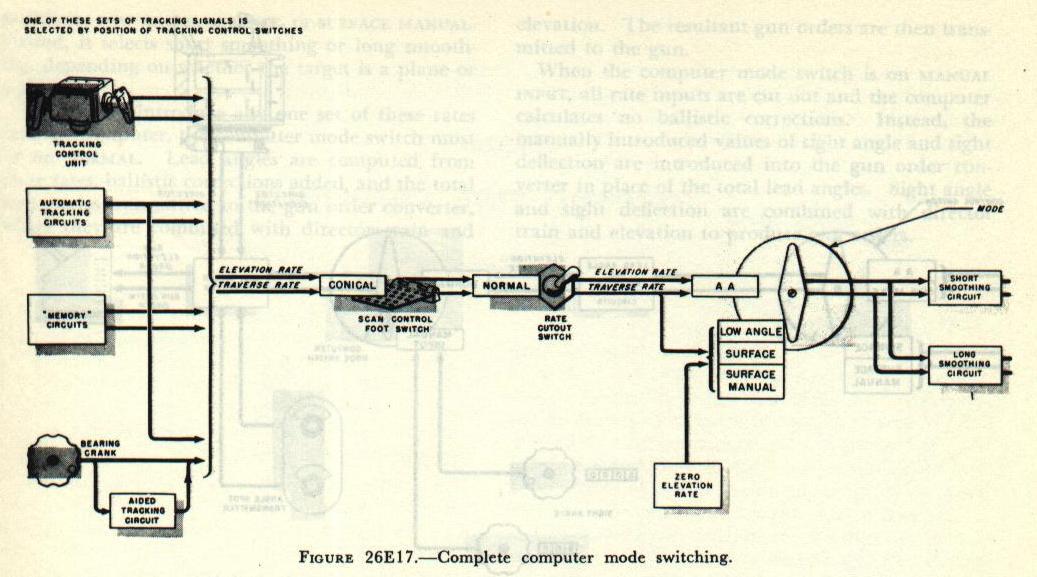

Computer mode switching. Figure 26E17 shows the controls affecting computer operation. The elevation and traverse rates introduced into the computer for computing lead angles are the same as those transmitted to the gyro unit for positioning the director. However, the computer does not receive slewing rates nor, generally, rates from the console cranks.
The only traverse and elevation rates received by the computer are those from: (1) the tracking control unit, (2) automatic tracking circuits, (3) memory circuits, and (4) the bearing crank when the mode control switch is set at SURFACE MANUAL. The mode control switch serves a dual function. First, it substitutes zero elevation rate when in positions LOW ANGLE, SURFACE, or SURFACE MANUAL. Second, it selects short smoothing or long smoothing, depending on whether the target is a plane or a ship.
In order to introduce any one set of these rates into the computer, the computer mode switch must be on NORMAL. Lead angles are computed from these rates, ballistic corrections added, and the total lead angles transmitted to the gun order converter, where they are combined with director train and elevation. The resultant gun orders are then transmitted to the gun.
When the computer mode switch is on MANUAL INPUT, all rate inputs are cut out and the computer calculates no ballistic corrections. Instead, the manually introduced values of sight angle and sight deflection are introduced into the gun order converter in place of the total lead angles. Sight angle and sight deflection are combined with director train and elevation to produce gun orders.