
Chapter 24 of Naval Ordnance and Gunnery, Volume 2 — Fire Control gives the analytical solution of the antiaircraft fire control problem, consolidated from three scanned sub-pages into one illustrated, scrollable page with a section table of contents. It treats target positioning (present, generated, and advance target position, and the rates of relative target motion), the ballistic computations that build up the lead angles (prediction, gravity superelevation, drift, wind, initial-velocity and air-density corrections), and gun positioning (sight angle and sight deflection, the make-up of gun orders, trunnion-tilt correction, and fuze settings).
Note on notation: this chapter uses the book’s symbols — a leading ₀ marks an initial (measured) value, c a generated value, d a rate, Δ an increment, and Σ a running sum. Key relations are reproduced as scanned equation panels where the original used built-up notation.
A. Target Positioning
24A1. Introduction
The antiaircraft fire control problem requires computations for its solutions which, although more complex, are in many respects similar to those already considered in the surface problem. The same basic fire control problem must be solved, namely: present target position must be continuously determined; ballistic corrections, whereby the axis of the gun bore is offset from the LOS, must be computed; motion of gun platform must be corrected for; gun orders must be made up; and provisions must be made for correcting an inaccurate solution.
The air problem is more complicated than the surface problem because, as a result of target elevation (E), it is three-dimensional; it may require the use of time-fuzed projectiles; and the problem develops with much greater rapidity due to higher target speeds.
In order to simplify the presentation, certain factors in the analytical solution are described in a manner which does not exactly agree with the process carried out by a computer. For reasons of space and weight limitations, the automatic solution includes empirical expressions and mathematical short cuts which are not here discussed, as they do not contribute to the understanding of the analytical solution of the AA problem.
In this chapter the line extending from the gun to the advance target position is called the line of fire (LOF). The vertical plane containing the LOF is called the plane of fire. The actual flight of the projectile is from the own-ship position to the advance target position. In the surface problem ballistics were based on the LOS, while in the AA problem the change in target position during time of flight (Tf) of the projectile is of sufficient importance to warrant computing ballistics on the basis of the LOF. This section of the chapter deals with target position in the solution of the AA problem. Subsequent sections will take up ballistic computations and gun positioning.
24A2. Target position in relation to time
In considering target positioning, it should be noted that we are actually concerned with the target’s position at three distinct times: (1) the present target position, (2) the target position at any given instant (generated target position), and (3) the target position at the end of a specific time (advance target position), this specific time being Tf.
24A3. Present target position
In the analytical solution, target position with respect to own ship is fixed by use of three coordinates: present range (R), relative target bearing (Br), and target elevation (E). These quantities are illustrated in figure 24A1, and are defined as follows:
R — Present range. The distance of target from own ship measured along the LOS.
Br — Relative target bearing. The horizontal angle between the vertical plane containing the fore-and-aft axis of own ship and the vertical plane containing the LOS, measured clockwise from bow of own ship.
E — Target elevation. The vertical angle between the horizontal and LOS.

Br and E can be determined by measuring the position of the LOS, while R can be measured by rangefinder or radar. As there is likely to be motion of own ship and target, successive instantaneous positions may be established by continuing to direct the LOS at the target and by measuring the present range.
24A4. Generated target position
In the equipment under discussion, present relative target position is generated by rangekeeper methods similar to those employed in the surface fire control problem. Generated relative target position is then used as the basis of the solution for sight angle (Vs), sight deflection (Ds), and fuze-setting order (F).
The generated target position can be expressed by the following equations:
cBr = ₀Br + ΣΔT(dBr) = ₀Br + ΣΔcBr
cE = ₀E + ΣΔT(dE) = ₀E + ΣΔcE
The initial values of R, Br, and E are obtained by measurement. Increments of time (ΔT) can also be considered as a measured quantity. This leaves the three rates, range rate (dR), angular bearing rate (dBr), and the angular elevation rate (dE) to be determined. This is done in two steps:
1. Resolve own ship’s motion into horizontal components and target’s motion into horizontal and vertical components of relative target motion.
2. Then resolve these horizontal and vertical components into three rates dR, dBs, and dE with respect to the LOS.
Resolution of own ship’s motion is accomplished exactly as in the surface problem. Ship’s motion is in the horizontal plane. Aircraft target motion cannot be resolved entirely into the horizontal plane, as the target may be climbing or diving.
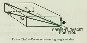
In figure 24A2 the vector representing target motion is labeled S, is with respect to the earth, and is resolved into two components, horizontal target speed (Sh) and vertical target speed (dH), (called rate of climb and would be negative if target is descending). Sh and dH are the horizontal and vertical components, respectively, of S.
In figure 24A3, Sh and dH are combined with figure 24A1, and these motions are resolved in the horizontal.
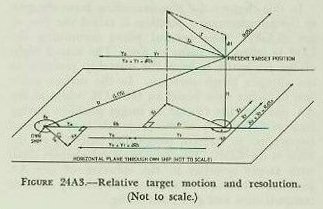
The LOS projected into the horizontal is called horizontal range (Rh). The horizontal range rate (dRh) is measured along this line. The linear deflection rate (RdBs) is measured at right angles to the vertical plane containing the LOS, and is measured in the slant plane through the LOS at the target. The complete solution for these last two mentioned rates (dRh and RdBs) follows. Both own ship’s speed (already in the horizontal) and the target’s horizontal speed component are resolved into two components in and across the LOS (Yo and Yt, Xo and Xt respectively) or:
RdBs = Xo + Xt = So sin Br + Sh sin A
The algebraic sign of the components can best be determined by inspection of a diagram of any particular problem. A component that tends to increase the basic coordinate is considered positive.
As yet the solution for present rates is incomplete. Direct range rate is defined as the rate of change of range along the LOS. Horizontal range rate (dRh) is not the same as direct range rate (dR), since it is not measured along the LOS. The change of bearing has to be converted to an angular rate of change which may be applied directly to initial bearing. A solution for elevation rate (RdE) must be developed, and it must also be converted to an angular rate. The completion of the solution with applicable formulas follows:
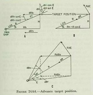
Range rate. Both dRh and dH are in the vertical plane through the LOS and are inclined to it by E and (90°−E) respectively. By inspection of figure 24A1, it can be seen that direct range rate is made up by resolving dRh and dH with respect to the LOS, or, by referring to figure 24A4 (A and B), it can be seen that
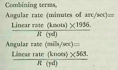
Converting a linear rate to an angular rate. The following equation may be used:
× 3.44 (minutes of arc/mil) to obtain the angular rate in mils
Bearing rate. However, dBs×ΔT cannot be combined directly with ₀Br to give cBr, since dBs is measured in the slant plane and ₀Br is measured in the horizontal plane. In order to convert dBs into an equivalent value in the horizontal plane (dBr) the linear rate must be divided by the horizontal component of R, which is Rh. See figure 24A1. It is evident that Rh = R cos E. Then, referring to figure 24A4 (C):
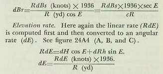
Now by multiplying the present rates by increments of time (ΔT) and combining the product with the quantities ₀R, ₀Br, and ₀E the equations for the generated target position mentioned above are obtained.
In a rangekeeper or computer it is more convenient to multiply by the reciprocal of the cosine (1/cos = sec) than to divide by the cosine itself. The Mark 1A computer was designed to use generated present range (cR) instead of observed present range, because at the time of design rangefinder ranges had to be used. Rangefinder ranging is necessarily intermittent. Continuous radar ranges of satisfactory quality are now available and are often introduced indirectly into the computing mechanisms by keeping the generated values equal to the observed.
24A5. Advance (predicted) target position
The present rates of relative target motion dR, dBr, and dE serve another purpose. Based on the assumption that these rates will remain constant for short periods of time, these present rates can be used to predict the target’s position at the end of time of flight (Tf) of the projectile. The results may be considered as determining an approximate line of fire. As previously mentioned, this LOF, because of high speed of the target, may be considerably different from the LOS. Ballistic computations are based on this LOF.
B. Ballistic Computations
24B1. Statement of the problem
The LOS, as roughly established in article 24A5, must further be corrected for the effects of gravity, drift, wind, loss of initial velocity (I.V.), nonstandard atmospheric conditions, and certain geometric errors introduced by the fact that the motion of the gun is limited to train in the deck plane and to elevation in a plane perpendicular to the deck.
Corrections for these effects and for relative target motion are summed up to form the two lead angles, one in the vertical plane and one in the slant plane. These lead angles are called sight angle (Vs) and sight deflection (Ds), respectively. Although computed and applied separately, together they represent the total lead angle, that is, the angle the gun bore axis must be pointed ahead of the present LOS to obtain a hit on a moving target.
Surface range tables provide data for the point of fall; that is the point at which the trajectory returns to the horizontal. This consideration is seldom of interest in AA fire, as the object is to produce a burst at some intermediate point of the trajectory to hit a target in the air. The trajectory OMT in figure 24B1 is the one that would be used against a surface target at T or an air target at M or M1 or any other point of the trajectory. No matter where the target is on OMT, the angle of departure, or vertical gun elevation (Eg) is the same. However, sight angle (Vs) and sight deflection (Ds) will have different values for each point on the trajectory, since these values are measured from the LOS, and the LOS is different for each elevated target position. OM is the LOS for a target at M, while OT is the LOS for a target at T. Vs and Ds depend upon both present range (R) and target elevation (E). Since corrections for wind and relative motion depend upon relative target bearing (Br), sight settings in any particular case also depend on Br. The problem is to determine values of Vs and Ds which will place the bore axis in the position which will produce the trajectory required to hit.
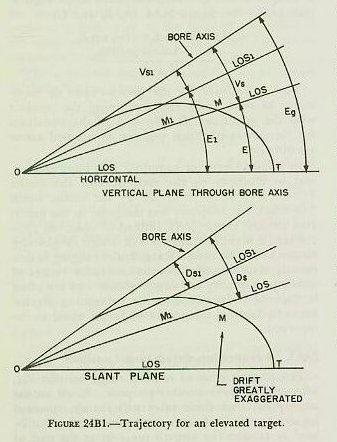
In the succeeding paragraphs it will be assumed that the trunnion axis is horizontal, and a closer examination will be made of the effects to be considered in determining the lead angles Vs and Ds. Consideration will be made for: (1) own-ship and target motion; (2) trajectory curvature caused by gravity and drift; and (3) effects of wind, I.V. variation, and air density variation.
24B2. Prediction of relative target motion and advance target position
During time of flight the target moves from the position it occupied at the instant of firing. The gun must be fired, not at present target position, but at the advance position the target will occupy at the end of Tf. The LOS is directed at the present position, so the gun must lead the LOS and the target, by corrections in elevation and deflection.
Relative target motion has been described by the linear rates dR, RdE, and RdBs. Predictions for relative target motion, then, may be expressed by the equations:
Vt (the predicted angular change, minutes of arc, in elevation during Tf) = (Tf/R2) × RdE × 1936
Dt (the predicted angular change, mils, in bearing during Tf) = (Tf/R2) × RdBs × 563
Note that the quantity R2, advance range, is now used to convert to angular rates. This is because it provides more accurate predictions of the target’s actual motion in elevation and deflection, and can be easily approximated as will be seen below.
In paragraph 24A4, the relationships between RdE and dE; RdBs, dBs, and dBr were shown. However, figure 24A4 (C) was slightly misrepresented in order to clarify the picture of these relationships to the solution. Actually, dR, RdE, and RdBs, being rates, have no terminus until combined with a definite “time” such as Tf. See figure 24B2 (A and B).
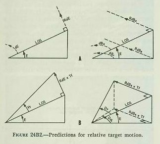
From the above, it is seen that the angular quantities, dE, dBs, and dBr, are angles subtended by RdE and RdBs at any instant. By multiplying RdE and RdBs by Tf, the angles Vt and Dth are formed. See figure 24B2 (B).
The predicted position of the target (see fig. 24B3) in relation to own ship is defined by the three coordinates:
1. Advance (or predicted) range R2.
2. Predicted relative target bearing Br2.
3. Predicted target elevation E2.
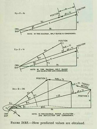
Note the numeral 2 is used to indicate predicted values describing the advance position. Approximate values for R2 and E2 are obtained by these equations:
E2 = E + Vt
The expression for deflection prediction Dt = (Tf/R2) × RdBs × K is measured in the slant plane. The value for predicted relative bearing must be measured in the horizontal. Therefore, Tf × RdBs is divided by horizontal range, R2 cos E2, giving Dth. Consequently:

24B3. Effect of deflection and elevation predictions on advance range
In the above equation, Rt does not take into account the fact that corrections for deflection and elevation have an effect on advance range; nor is the effect of a deflection setting on elevation shown in the expression for Vt.
Figure 24B4 (A) shows the effect of deflection on advance range. With target angle 90° and the range rate 0, the predicted range would lie on the dotted circle instead of at the desired point on the straight line. The range correction due to deflection rate is shown by the heavy arrow, and is labeled Rx.
Figure 24B4 (B) shows an additional but similar correction required in the AA problem. Here, for simplicity, a target is climbing perpendicular to the LOS, which gives dR = 0 and Rt = 0. The target again follows a straight course, so the error is the difference between the straight line and the circle, again shown by a heavy arrow and labeled Re. This is the range correction due to an elevation rate.
Although the angle made by the target and the LOS in both instances was taken as 90°, it should be evident that the two effects described will be present no matter what the target angle may be.
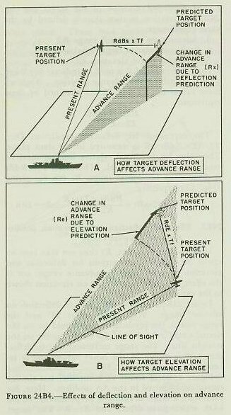
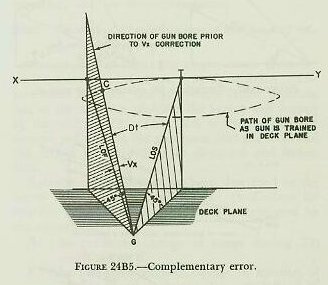
Figure 24B5 shows another error of size large enough to need correction in the AA problem. It is called complementary error and is the change in elevation caused by the deflection prediction (Dt) and E. Assume the target, T, is at the elevation 45° and is flying on a straight course at right angles to the LOS along XY. The figure shows that if a train correction only were made to compensate for target deflection the predicted LOF (GC in the figure) would not run to the target, but would pass above it. The deflection of the target has made necessary a smaller angle of elevation. This change in elevation is complementary error (Vx), and occurs because the gun’s roller path is in the deck plane, and, as the gun is trained, its bore axis follows the path of a cone. Vx is always a negative correction.
24B4. Correction for effect of gravity
As in the surface problem, it is clear that the gun cannot be pointed directly at the advance target position, because the pull of gravity on the projectile during the time of flight will cause the trajectory to curve downward. The correction for gravity effect in the air problem is called superelevation (Vf). The angle the gun must be elevated to compensate for the effect of gravity depends on three factors: range, initial velocity, and target elevation. Superelevation varies inversely with I.V., because an increase of I.V. decreases the Tf for a given range, and gravity has less time to act. Superelevation increases with range, because range and time of flight are closely related. Superelevation varies as the cosine of the angle of elevation, decreasing as the gun is elevated. See figure 24B6. For a gun of given I.V., superelevation is considered to be a function of target elevation and range. In a computer, Vf is computed by a cam.

24B5. Drift
The correction for drift measured in the slant plane through the predicted target position (Dfs) varies from point to point along the trajectory and must be computed for this predicted position of the target. Suitable curves, having drift, time of flight, and predicted target elevation as arguments are available. From these, the proper value of Dfs for a given problem may be obtained and a suitable drift cam may be cut for furnishing the proper value in a computer. Drift correction (Dfs) is always a minus quantity.
24B6. Wind
Figure 24B7 is a diagram of the computation of wind correction in the air problem. As in the surface problem, only horizontal wind is considered, and its value is based upon ballistic wind data obtained by aerological observations. However, because of the large probable difference between the LOS and LOF, wind correction is computed with respect to the LOF. Since own-ship motion has been considered as equivalent target motion in obtaining relative motion, apparent wind must be used in making wind corrections. The following definitions and symbols are essential to the computation and understanding of figure 24B7.
Cwg — Predicted wind angle. The horizontal angle between the direction toward which the true wind is blowing and the plane of fire, measured clockwise from the direction toward which the wind is blowing to that part of the plane of fire between the wind and own-ship vectors.
Xog — Cross component of own-ship velocity. The horizontal component of own-ship velocity perpendicular to the plane of fire. Xog = So sin Br2.
Xwg — Cross wind. The horizontal component of true wind perpendicular to the plane of fire. Xwg = Sw sin Cwg.
Xwgr — Apparent cross wind. The horizontal component of apparent wind perpendicular to the plane of fire. Xwgr = Xog + Xwg.
Yog — Line component of own-ship velocity. The horizontal component of own-ship velocity in the plane of fire. Yog = So cos Br2.
Ywg — Range wind. The horizontal component of true wind in the plane of fire. Ywg = Sw cos Cwg.
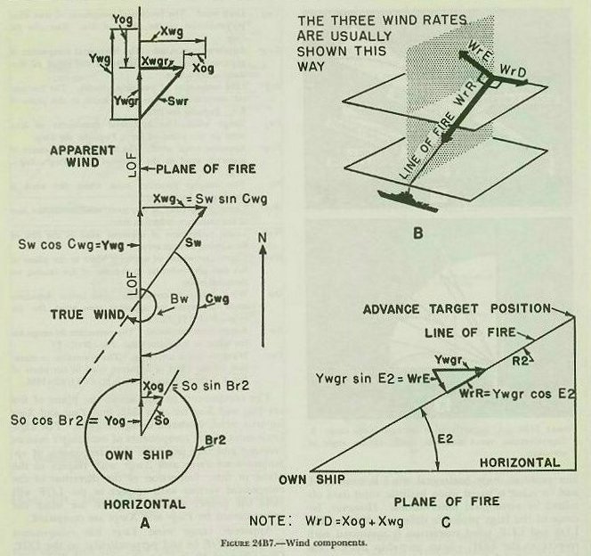
Ywgr — Apparent range wind. The horizontal component of apparent wind in the plane of fire. Ywgr = Yog + Ywg.
Bw — The compass direction from which the wind is blowing.
WrD — Linear component of apparent wind across the line of fire causing a deflection error.
WrR — Linear component of apparent wind in the line of fire causing a range error.
WrE — Linear component of apparent wind in the plane of fire and perpendicular to the line of fire causing an elevation error.
Dw — Wind deflection correction. The lateral deflection angle to correct for apparent cross wind. Dw (in mils) = WrD × Tf/R2 × 563.
Rw — Range wind correction. The correction in range for the effect of apparent wind. Rw = WrR × Tf.
Vw — Wind elevation correction. The correction to elevation for the effect of apparent wind in the plane of fire. Vw (in minutes of arc) = WrE × Tf/R2 × 1936.
The components in and across the plane of fire are Yog and Xog for own ship, and Ywg and Xwg for true wind, as shown in figure 24B7. The algebraic sums of the components of own ship’s motion reversed and true wind are the components of apparent wind Ywgr and Xwgr with respect to the plane of fire. Inspection of the direction of the component vectors with respect to the LOF will yield the proper algebraic sign to use when the errors caused by Ywgr and Xwgr are computed.
Apparent range wind Ywgr has components WrR and WrE in and perpendicular to the LOF. One effect of WrR is to alter time of flight. As WrR opposes projectile motion, Tf is increased. Tf must be corrected for range wind. Another effect of WrR is to alter the range attained by the projectile when fired at a given angle of departure. A range wind correction, Rw, will correct for this error. It is evident that to obtain a given range with WrR acting against the projectile a greater angle of elevation and a greater time of flight are required.
The component WrE will also influence the trajectory. If the target is at high elevation and the wind is blowing against the projectile toward the gun, WrE will tend to elevate the trajectory. A correction to gun elevation called Vw, wind elevation correction, must be applied to counteract the error caused by WrE.
The apparent cross wind component, WrD, causes deflection of the projectile. Wind deflection correction, Dw, is applied to sight deflection to compensate for this effect.
24B7. Corrections for I.V. variations
Not all projectiles can be fired at the designed initial velocity, because of gun erosion and changes in temperature of powder charges. An altered I.V. will change the trajectory, in that a projectile fired below designed I.V. will travel more slowly and will drop sooner than a projectile fired at or above designed I.V. Two corrections are necessary, Rm, range correction for I.V. variations, and Vfm, elevation correction for I.V. variations. Rm is a function of I.V. variation and time of flight. Vfm is a function of I.V. variation, R2 and E2.
24B8. Correction for air density variation
Air density higher than standard would result in a projectile’s falling short of a desired range; or, in contrast, an air density lower than standard would result in a projectile’s going beyond (over) a target at the specified range. Then, to have a projectile reach a desired range when air density is higher than standard, and to counteract the resulting increase in time of flight, a more elevated trajectory would be required. The elevation correction, Vu, is a function of the percent of variation from standard air density, and is a function of R2 and E2.
Practically, this correction does not exist in the mechanical solution of the AA problem. It is computed from a range table or nomogram and is either entered as a spot or converted to I.V. variation.
24B9. Ballistic data
A trajectory graph appended to OP 551, 2nd rev., shows the trajectories of the 5"/38 gun when fired at various angles of departure under standard conditions. Any variation from these conditions results in modifications of the trajectory. While it would be possible to make a similar graph for any other particular set of conditions, it is obviously impracticable to do so for a wide variety of sets of conditions. Instead, the graph as shown serves as the basis for many of the ballistics which correct for variations. Among items directly available from this graph for any point on a given trajectory are:
1. Time of flight and fuze setting.
2. Height. Read from the vertical scale at the left edge of the drawing.
3. Horizontal range. Read from the range scale at the bottom.
4. Slant range. Obtained by using dividers and the horizontal range scale.
5. Target elevation (position angle). Measured by laying straight edge through origin and point on trajectory, and reading angle of position scale.
6. Superelevation. Angle at which gun must be elevated above predicted target position to allow for trajectory curvature in the vertical plane caused by gravity.
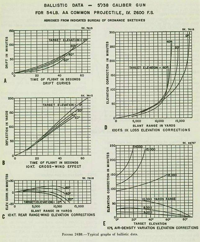
Some corrections for variations from standard conditions are provided on graphs, generally about 18 inches by 24 inches in size, issued by the Bureau of Ordnance. To acquaint the student with the type of information available, excerpts from some of the graphs for the 5"/38 gun are reproduced in miniature in figure 24B8.
C. Gun Positioning
24C1. Summary of sight deflection and sight angle
Any error in gun positioning not accounted for by the preceding discussion can, in theory, be accounted for by the application of a deflection spot (Dj) and an elevation spot (Vj) of suitable size.
where Dt is deflection prediction, Dw is wind deflection correction, Dj is deflection spot, and Dfs is drift correction.
where Vt is elevation prediction, Vw is wind elevation correction, Vj is elevation spot, Vfm is elevation correction for I.V. variation, Vu is elevation correction for air density variation, Vf is superelevation, and Vx is complementary error.
Also, R2, which enters into the determination of the ballistics listed above, may be expressed as:
where cR is generated present range, Rt is range prediction, Rw is range wind correction, Rj is range spot, Rm is range correction for I.V. variation, Rx is change in advance range due to deflection prediction, and Re is change in advance range due to elevation prediction.
24C2. Makeup of gun orders
Under normal conditions, the deck is not horizontal and guns are positioned by gun orders made up in a computer. These gun orders are based on the director LOS; they include Vs and Ds, which must continuously be corrected for inclination of the deck. This correction is known as trunnion tilt correction. Since the gun’s motion is limited to train in the deck plane and to elevation in a plane perpendicular to the deck, gun orders must be computed in those planes and must be based on the standard reference of the ship. Trunnion tilt corrections assume greater importance in AA fire than in surface fire, because of higher gun elevation. These corrections are not included in Vs and Ds, because of the rapidity with which they change, but are computed and included in gun train and gun elevation order.
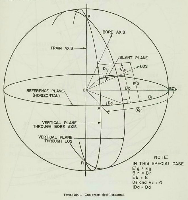
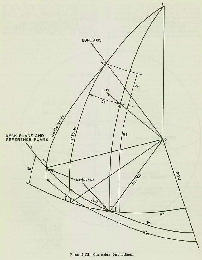
Accordingly, gun elevation order E′g contains (1) the elevation of the director LOS above the deck plane Eb, (2) the vertical offset Vs to account for prediction and ballistics, and (3) the trunnion tilt correction in elevation Vz, or,
Gun train order is made up of (1) director train B′r, (2) the lateral offset Ds to account for prediction and ballistics, and (3) trunnion tilt correction Dz. Actually Ds is in the slant plane and must be projected into the deck plane as jDd to be made usable for the gun, or,
These quantities can be seen in figure 24C1 for a horizontal deck, and figure 24C2 for an inclined deck.
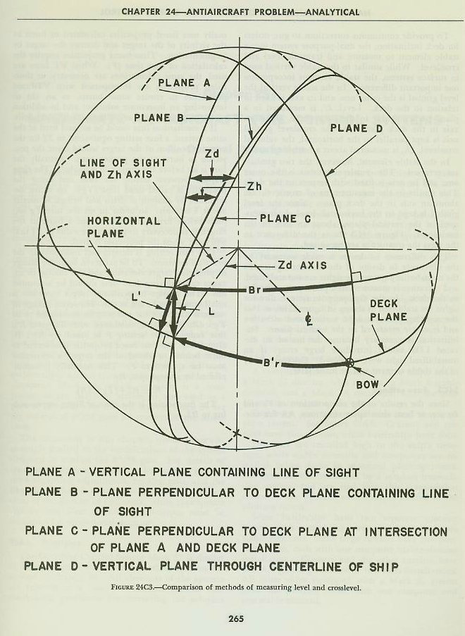
To provide continuous corrections to gun orders for deck inclination, the dual-purpose system uses a stable element to measure and transmit level and crosslevel. While similar to the stable vertical used in surface systems, the stable element incorporates one important difference. In the stable vertical the level gimbal is the outer one, and its axis is fixed in relation to the deck. Level, L′, is measured in a plane perpendicular to the deck plane, about an axis in the deck plane. As the crosslevel gimbal axis is kept parallel to the horizontal, the value of crosslevel, Zh, is measured about a horizontal axis.
In the stable element, however, the two gimbals are reversed. The crosslevel gimbal is the outer one, and its axis is fixed with respect to the deck. This results in the measurement of crosslevel, Zd, about an axis in the deck plane. Since the level gimbal is kept in the horizontal, level, L, is measured in the vertical plane, about an axis in the horizontal. Figure 24C3 shows the difference in the ways the quantities are measured.
This difference in design is made necessary by the difference in design of the director sights. In the main-battery system the sights are not stabilized, and elevation is measured in a plane perpendicular to the deck. In the dual-purpose system, director sights are stabilized as shown in figure 25B6, so that the sighting plane is kept vertical and elevation and level are measured in the vertical plane. Stabilization is necessary because the use of an elevated LOS would introduce large errors if an unstabilized sight were employed. Extensive study of the stable element will be made later.
24C3. Fuze settings
Since the results of the computations of Vs and Ds are, at best, close approximations, AA fire normally uses fuzed projectiles calculated to burst in the vicinity of the target and destroy the target by fragmentation. Time-fuzed projectiles require the calculation of fuze time (F). When VT fuzes are used, the same calculations are necessary, as time-fuzed projectiles are interspersed with VT-fuzed projectiles to ensure some bursts, as an aid to improving an inaccurate solution; and in addition mechanical time fuzes are still used with star shells.
If a mechanical fuze could be set and fired at the same instant, a fuze setting equivalent to Tf for the advance position of the target would cause the projectile to burst at the proper time. Actually the fuze is set before the projectile is loaded. The time elapsed between setting the fuze and firing the projectile is called dead time (Tg). Its value, determined by analysis of drills and firings, is usually about 4 seconds. In order to set the fuze Tg seconds before firing and still obtain a burst at the target, it is necessary to predict the value of Tf that will exist when the projectile is fired.
This fuze setting is determined indirectly in the practical solution. To be accurate, both the change in predicted target elevation and the change in advance range during dead time should be accounted for. The change in predicted target elevation is small enough to be neglected. However, change in range is corrected for and may be considered to be Tg × dR. This value, combined with R2, gives R3, fuze range. Fuze setting F is based on R3. If, after firing, the time-fuzed projectile is observed to burst behind or ahead of the target, a correction must be applied to F. This normally is accomplished by a range spot, Rj.
The fuze setting is the time of flight corresponding to R3.