
Chapter 25 of Naval Ordnance and Gunnery, Volume 2 — Fire Control covers linear-rate antiaircraft fire control systems — chiefly the Gun Fire Control System Mark 37, the standard dual-purpose system of the World War II and early Cold War fleet. Consolidated from four scanned sub-pages into one illustrated, scrollable page with a section table of contents, it describes the system in general, its director (the Mark 37 director), its computer (the Mark 1A), and its Mark 6 stable element.
Note on notation: this chapter uses the book’s symbols — B′r director train, Eb director elevation, R present range, L level, Zd crosslevel, and a leading Δ (“increments”) for a generated change such as ΔcR, ΔcE, ΔcB′r.
A. General Description
25A1. Introduction
Antiaircraft fire control systems of various types are designed to control guns ranging in size from light machine guns through 8"/55 rapid-fire guns. For convenience, these systems will be considered in two classes: those which determine rates of change of relative target motion as linear rates (linear-rate systems), and those which measure the angular velocity of the line of sight by gyroscopic means (relative-rate systems), described in chapter 26.
The Gun Fire Control System Mark 37 is the most significant example of the linear-rate system. It is installed on destroyers, cruisers, carriers, battleships, and some types of large auxiliaries. It is the primary means of control of the 5"/38, 5"/54, and 6"/47 guns for both surface and antiaircraft fire; it may be used, with appropriate cross connections, to control heavy machine-gun mounts, or major-caliber surface-type guns in special uses. The Computer Mark 1A, which normally is a component of the Mark 37 system, is also used as a part of the Gun Fire Control System Mark 54 for the control of 8"/55 guns on cruisers of the Salem class.
The discussion in this chapter, unless otherwise stated, is limited to the modifications of the system designed to control the 5"/38 gun. For details of other modifications, as well as for specific instructions regarding adjustments, repairs, tests, and the like, the student is referred to appropriate publications of the Bureau of Ordnance, while appropriate OpNav and Fleet training publications must be consulted for operational doctrine.
25A2. Principles
The Gun Fire Control System Mark 37 is similar in many respects to the main-battery systems described in chapter 20. All elements of the systems are referred to a common reference system, with mechanical provisions for correcting the solution for the effects of roller-path inclination and parallax. Inclination of the deck plane from the horizontal is measured and compensated for by a gyroscopic stable element.
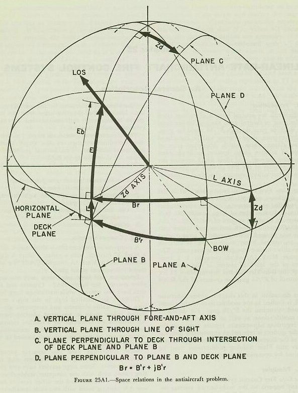
The director system measures target position in three coordinates: range, relative target bearing, and target elevation. Fundamental geometric relations are shown in figure 25A1.
The primary functions of the system are to provide:
1. Continuous automatic gun positioning.
2. Continuous automatic fuze setting.
3. Continuous sight-angle and sight-deflection indication at the guns.
4. Continuous-aim, selected-level, and selected crosslevel fire.
5. Star-shell fire control.
25A3. Component units
A complete system consists of three major units: a Mark 37 director, with a radar, a Mark 6 stable element, and a Mark 1A computer, with the associated instruments at the gun.
Destroyers and large auxiliaries carry one complete system. See figure 25A2. Cruisers and carriers have two systems, while battleships have four.
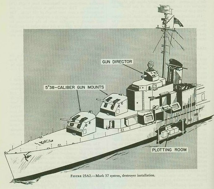
Directors are installed high in the ship’s structure, while stable elements and computers are installed below decks in protected plotting rooms. All elements are connected by a synchro transmission system, and are tied into this transmission system at one or more switchboards located in the plotting rooms.
Some battleships have two separate plotting rooms, each containing two computers and two stable elements. Some large carriers have two plotting rooms, each with one computer/stable-element installation. Cruisers and the other carriers have one AA plotting room with two such installations. All other ships equipped with a Mark 37 system have one plotting room, with one computer and one stable element.
Normally, each director in a multiple installation controls a designated group of guns and is connected to a designated computer. However, switching arrangements permit any director to control any or all guns and to be connected to any one of the computers. Also, on many ships, the Mark 37 director can control part or all of the heavy machine-gun battery.
On cruisers and battleships, the Mark 37 director can supply director train and director elevation to the main-battery rangekeeper. In addition, the three major units of the Mark 37 system can control the main battery in AA fire, using pre-selected fuze settings.
25A4. Parallax and roller-path corrections
In order to obtain maximum flexibility, all train and elevation orders and measurements are based on a common reference system. Range errors due to horizontal distances between units of the system are not considered. However, roller-path inclination, horizontal parallax, and vertical parallax are accounted for.
Roller-path inclination. A roller-path tilt corrector or compensator to correct for roller-path inclination is installed at each gun. On ships with more than one director, each has a roller-path tilt corrector. When there is only one director, its roller path is the reference plane and it has no tilt corrector.
Horizontal parallax. The reference point in train is usually at the director, if there is only one; or, if more than one, then midway between the forward and after directors on their centerline. The computer transmits the value of parallax correction for a 100-yard horizontal base (Ph) to all guns and directors. In the train indicator-regulator of each unit, this parallax correction for 100 yards base is converted (by a simple gear ratio) to correction for the unit’s actual distance from the reference point. Where only one director is installed, the center of its roller path is taken as the reference point. In this situation, the director needs no parallax correction and has no parallax mechanism.
Vertical parallax. The base length or vertical parallax is the distance between the director telescopes and the mean gun-trunnion height. Individual trunnion-height variations from the mean are small enough to neglect. In multiple installations, telescope-height variations between directors are also neglected. A unit vertical base length, usually 30 feet, is used. Parallax (Pe) based on this 30-feet height is calculated in the computer and sent to the guns as part of gun elevation order. Hence, no special vertical parallax mechanism at the mounts is needed.
A special case exists on large carriers such as the Essex and the Midway classes. On these ships, horizontal distances are so great that a vertical parallax correction for horizontal base length (Pv) is necessary. This correction is calculated in the computer for a unit base length of 100 yards. The result is sent to the guns as a separate quantity. At each mount, a parallax unit in the elevation indicator-regulator converts the unit value of parallax to the proper amount for the actual base length. The resulting correction is applied to the gun elevation response.
25A5. Flow of information
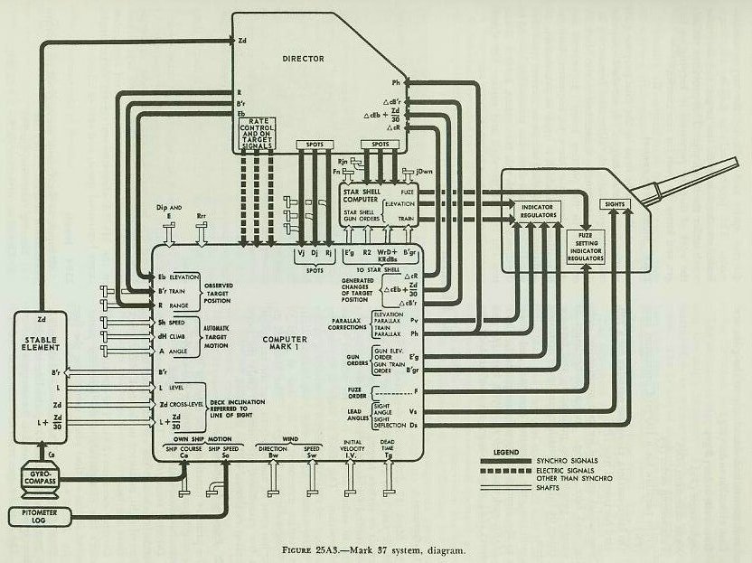
Figure 25A3 is a schematic diagram showing the principal interconnections of a single Gun Fire Control System Mark 37. All electrical circuits between units of the system pass through the fire control switchboard.
The director, in addition to telescopes, carries a rangefinder and radar equipment. This equipment is used to measure and transmit to the computer: director elevation (Eb), director train (B′r), and present range (R). The control officer in the director may estimate target angle (A), target horizontal speed (Sh) and rate of climb (dH). When the computer is in the automatic method of rate control, it is not necessary to make these estimates. The control officer sends these values by telephone to the computer operators. Hand-operated transmitters in the director provide electrical transmission of elevation, deflection, and range spots to the computer.
The stable element, a unit very similar to the stable vertical studied in chapter 20, measures level angle (L) and crosslevel angle (Zd). These values are sent mechanically to the computer. A third value, L + Zd/30, which is explained fully in article 25B14, is also sent mechanically to the computer. Here it is added to ΔcE, forming ΔcE + L + Zd/30, which is transmitted electrically to the director. In the director, ΔcE + L + Zd/30 is used to keep the line of sight automatically on the target in elevation. Crosslevel (Zd) is transmitted electrically from the stable element to the director to stabilize the optics and radar antennas in crosslevel.
Electrical inputs to the computer come from the director, the ship’s gyro compass, and the pitometer log (speed). As explained above, inputs to the computer from the stable element are mechanical. Finally, the computer operators apply various manual inputs to the instruments. The quantities computed and transmitted electrically to the guns are:
1. Gun elevation order (E′g).
2. Gun train order (B′gr).
3. Sight angle (Vs).
4. Sight deflection (Ds).
5. Fuze setting order (F).
6. Train parallax for a 100-yard horizontal base (Ph).
7. On large carriers, elevation parallax for a 100-yard horizontal base (Pv).
These values are used for gun positioning, sight setting, and fuze setting. Indicator-regulators at the mounts provide gun positioning and fuze-setting either by fully automatic means or by matching pointers.
In addition, the computer generates and transmits to the director changes in range (ΔcR), elevation (ΔcE), and train (ΔcB′r). With level (L) and crosslevel (Zd), these changes are used to hold the director optics and radar on the target continuously. This process includes keeping the rangefinder wander marks on the target and the radar notch under the target pip. This provision reduces the work of director personnel in keeping on target, and forms the basis for rate control.
25A6. Illumination control
Star shells can be fired by the dual-purpose guns to illuminate surface targets. A star-shell computer calculates gun train, elevation, and fuze-setting orders. This instrument is attached to the Mark 1A computer in the plotting room. It receives mechanically, from the Mark 1A computer, basic information upon which it bases its calculations. In addition, the star-shell computer receives spots electrically from a star-shell spot transmitter located in the director. With this instrument, a Mark 37 system can control star-shell and surface fire simultaneously on the same target.
B. Director
Section B describes the Mark 37 Gun Fire Control Director in detail — its design, inputs and outputs, component instruments, operating modes, train and elevation control mechanisms, crosslevel stabilization, radar integration, spotting, and multiple-director installation corrections. The Mark 37 was the standard dual-purpose director for the U.S. Navy’s 5"/38, 5"/54, and 6"/47 gun batteries from World War II through the early Cold War era.
25B1. General
The Mark 37 director is designed to control 5"/38, 5"/54, or 6"/47 dual-purpose guns against either air or surface targets, and to provide illumination control for star shells. It can be trained 375 degrees in either direction from its neutral or secured position. The limit in train is imposed by the amount of twist the director’s connecting cables can safely stand. In elevation, mechanical limit stops restrict movement of the line of sight to +110 degrees and −25 degrees. The Mark 37 director has some 92 modifications, but the variations, with few exceptions, are minor. Only the more important variations will be discussed.
25B2. Primary functions
The primary function of the director is to determine target position, according to the three coordinates that determine the line of sight:
1. Director train (B′r). The angle between the fore-and-aft axis and the vertical plane containing the line of sight, measured in the deck plane, clockwise from the bow.
2. Director elevation (Eb). The elevation of the director’s line of sight above the reference plane, measured in the vertical plane containing the line of sight. Eb = E + L.
3. Present range (R). The distance of the target from own ship, measured along the line of sight.
These quantities are used in the computer as: (1) the basis for gun train and elevation orders; (2) part of the initial computer set-up; and (3) a check on the accuracy of the solution generated by the computer.
25B3. Secondary functions
The director’s secondary functions can be summarized by saying that it is the control station for the entire fire control system. When the system is functioning as designed, all units operate by remote control from the director. When changes in the problem set-up are necessary, the director crew can accomplish them by remote control. In order to control the entire system, the control officer can:
1. Make initial estimates of target angle, target horizontal speed, and rate of climb (used for manual rate control).
2. Spot service projectile fire and transmit these spots.
3. Spot star-shell fire and transmit these spots.
4. Control rate calculations in the computer by having his pointer, trainer, and radar or rangefinder operator close their rate control keys or buttons. This will cause the rate control mechanism in the Mark 1A computer to correct target angle, target horizontal speed, and rate of climb.
25B4. Inputs
All inputs to the director are received via synchro transmission systems. They are:
1. Bearing correction (ΔcB′r).
2. Elevation correction (ΔcE + L + Zd/30).
3. Range correction (ΔcR).
4. Crosslevel (Zd).
5. Train parallax for 100-yard horizontal base (Ph) (in multiple-director installations only).
25B5. Outputs
Normally, all outputs from the director are sent via synchro transmission systems. These outputs are:
1. Director train (B′r).
2. Director elevation (Eb).
3. Observed present range (R).
4. Range spot (Rj).
5. Deflection spot (Dj).
6. Elevation spot (Vj).
7. Rate control or on-target signals for range, elevation, and bearing. Trainer’s on-target signal is also the remote control key for starting the computer time motor.
8. Star-shell range spot (Rjn).
9. Star-shell elevation spot (E′jn).
10. Star-shell deflection spot (B′jn).
25B6. Components of the director
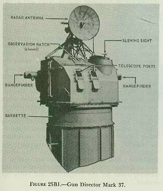
The external appearance of the director is shown in figure 25B1. The most important instruments are the two telescopes, the rangefinder, and the radar. These are essential to the primary functions of the director: measuring director train, director elevation, and present range.
The director is supported on a foundation built into the ship’s structure. This foundation is so machined as to reduce roller-path tilt to a minimum. The principal supporting elements are the base ring, the carriage, and the shield. The shield is attached to the carriage, which is supported by roller bearings on the base ring. The base ring rests on the director foundation.
The personnel (six or seven men) enter the director through the foundation and base ring, passing through hatches in the floor of the carriage. The shield has one or two observation hatches in the top. There are two telescope ports in the front plate and a vertical slot in each side plate for the protruding ends of the rangefinder. Shield thickness varies between the thin, weather-protective type for destroyers, and the heavy, splinter-proof 1½-inch thick type on battleships. Telescope port covers are handwheel-operated, and on heavier shields so are the observation hatch covers.
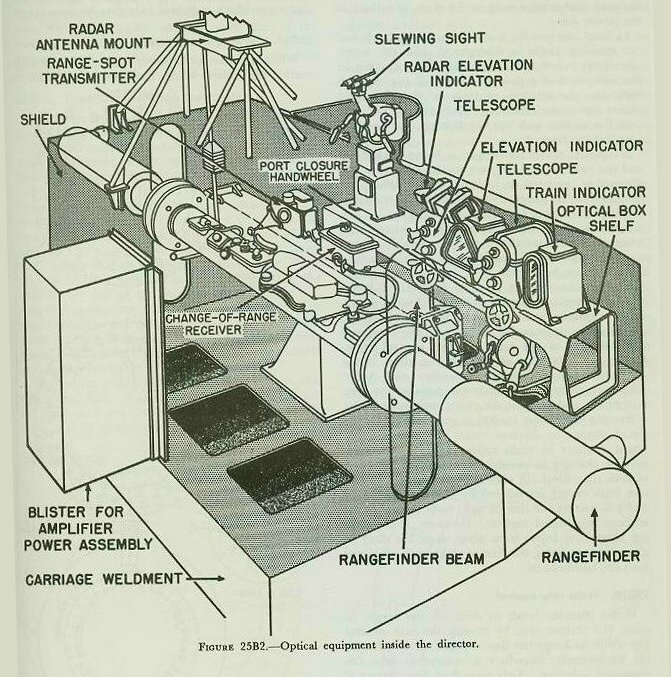
In most modifications of the director, the shield and carriage support the following component parts (some shown in figures 25B1 and 25B2):
1. Two Movable-Prism Telescope Mark 60.
2. Slewing sight.
3. Stereoscopic Rangefinder, 15-foot Base, Mark 42, and its carriage.
4. Change-of-range receiver.
5. Crosslevel gear and power drive.
6. Training gear with both manual and power drive.
7. Elevating gear with both manual and power drive.
8. Director train receiver-regulator.
9. Director elevation receiver-regulator.
10. Director crosslevel receiver-regulator.
11. Spot transmitter (bearing and elevation).
12. Range-spot transmitter.
13. Star-shell spot transmitter.
14. Roller-path tilt corrector (in multiple installations).
15. Horizontal-parallax mechanism (in multiple installations).
16. Radar antennas, control equipment, and indicators.
17. Target-acquisition equipment.
25B7. General operation
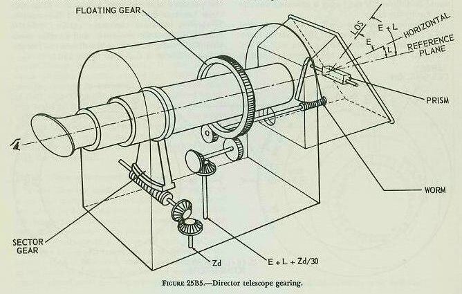
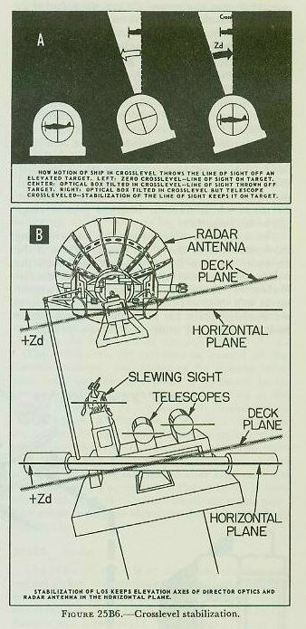
The two telescopes are mounted in housings called optical boxes. These boxes are rigidly secured to a transverse frame called the optical box shelf at the front of the director, which can be seen in figure 25B2. Within the optical box, each telescope is supported in bearings so that it can rotate about its longitudinal axis, which is parallel to the director roller path at the time of installation. The line of sight is moved in elevation by rotation of a prism within the telescope. The axis of the prism is perpendicular to the longitudinal axis of the telescope and parallel to the horizontal cross-hair. The operating principles of the telescope are illustrated in figure 25B5. The crosslevel power drive is geared to both telescopes and turns them about their longitudinal axes. The purpose of this arrangement is to keep the prism axes horizontal, so that the prisms always rotate in a vertical plane. This process is called stabilization in crosslevel.
The rangefinder is installed in a cradle called the rangefinder beam, which in turn is supported in a stand. The stand allows the beam to rotate about an axis lying in the sight plane, parallel to the roller path. The crosslevel power drive is geared to the beam and keeps it stabilized in crosslevel, so that the longitudinal axis of the rangefinder is always horizontal. The radar antenna is similarly stabilized.
The line of sight is kept on the target in train by turning the entire director on its roller path. The amount the director is turned from the fore-and-aft axis of the ship is a measure of director train (B′r). Elevation of the line of sight is accomplished by rotating the telescope prisms and by rotating the rangefinder about its longitudinal axis. Rotation of the radar antenna in elevation parallels rotation of the optics. The amount of rotation is the measure of director elevation (Eb).
Train and elevation of the director line of sight are controlled by mechanisms which provide for: (1) automatic (or remote) control of the power drive, modified as necessary by the handwheels; (2) local operation of the power drive by means of the handwheels; and (3) manual operation by direct gearing from the handwheels. Train can be accomplished by one of the three means listed above, while elevation is being accomplished by the same means or by either of the remaining two.
The crosslevel drive holds the sight plane vertical. The Mark 37 director, unlike the main-battery director, has no crosslevel telescope or other means of standby operation in crosslevel.
25B8. Personnel
Each man of the director crew should be trained to handle any station, so the director can continue to function in the event of a casualty. The personnel act as lookouts through the hatches until they have a target to track.
The control officer is in charge of the entire system. He supervises the director crew, the operators of the computer and stable element, and the crews of guns controlled by his director. He designates the target to his group and, if necessary, estimates target angle (A), target horizontal speed (Sh), and rate of climb (dH). These estimated quantities he telephones to the computer. The control officer also may make and transmit elevation and deflection spots. He issues battle orders via telephone or over the 17MC announcing system, and may control the firing circuit with a portable firing key.
The pointer and trainer keep the director line of sight on the target by turning their handwheels as necessary. They can rate control in elevation and train. Each has a firing key that can be selected to control the firing circuit. Normally, both act as talkers for the control officer.
The rangefinder operator mans the rangefinder and can make range spots in antiaircraft fire. In surface fire he may spot in both range and deflection. Also, he may rate control in range. When the rangefinder is not used, the rangefinder operator assists the radar operator.
The radar operator controls the operation of the Radar Mark 25. He supervises the pointer and trainer in their use of the elevation and train radar scopes. He operates the radar in range, and may rate control in range. In addition, he assists the rangefinder operator when the radar is not in use.
The illumination officer, if one is assigned, acts as assistant control officer and talker for the control officer. He supervises the rear half of the director. He controls any guns firing star shells. Also, when not concerned with illumination, he is available as a relief for any station.
25B9. Train control
In front of the trainer is a selector lever with which he chooses one of three designated methods of operation: AUTOMATIC, LOCAL, or MANUAL. In MANUAL, the trainer’s handwheels are geared directly to the training circle and he supplies the motive power. This method is slow and arduous, and is used only in the event of failure of the power drive.
In LOCAL, the gearing between the handwheels and the training circle is disengaged, and the handwheels are connected to the stator of a synchro in the train receiver-regulator. Through the receiver-regulator, the synchro controls an electric motor which drives the director. Thus the trainer controls the motion with the handwheels, but power is supplied by the motor.
Normally, when the target is being picked up and the problem is being set on the computer, the director is operated in LOCAL in train. When the computer starts generating a solution, it transmits bearing correction (ΔcB′r) to the director. Then the trainer shifts his selector lever to AUTOMATIC. After an initial solution has been obtained, local control is used only if transmission of ΔcB′r fails or if targets must be shifted.
Shifting the selector lever to AUTOMATIC leaves the handwheels connected to the synchro in the receiver-regulator, as in LOCAL. In addition, electrical transmission of ΔcB′r from the computer is connected to the same synchro control transformer. The output of the synchro, then, is the algebraic sum of handwheel motion and ΔcB′r. This sum controls the receiver-regulator, the electric motor, and thus the director’s position in train.
Bearing correction (ΔcB′r) is the increment of computed change in director train. It takes into account changes in train caused by relative target motion, changes in own ship’s course, and the effect of deck tilt. Deck-tilt correction is required to correct train errors introduced by roll and pitch. If ΔcB′r is correct, the line of sight stays on the target without handwheel motion. However, if the bearing correction input is in error, it is the duty of the trainer to bring the line of sight back on target with the handwheels.
25B10. Train rate control
If the director tends to drift off the target in train, the trainer can, by closing the rate control key while he keeps the line of sight on target with his handwheels, introduce a correction into the computer solution. This procedure is necessary if one of the quantities A, Sh, or dH is in error, or if there is a change in target course or speed. If the target becomes obscured, the trainer allows ΔcB′r to continue to drive the director and sends no rate control signal until the target reappears.
Rate controlling can also be accomplished by the computer operators. The director trainer holds his key closed when on target as in automatic rate control; however, his key actuates a signal at the computer which indicates only that he is on target.
25B11. Slewing the director
When the director is power driven (LOCAL or AUTOMATIC), the control officer may slew the director in train and elevation. He closes a key on the grip and points the slewing sight (illustrated in figure 25B2) at the target. By this procedure, control of the director is taken away from the pointer and trainer, and the director is driven at high speed until its line of sight coincides with that of the slewing sight. The control officer uses this sight to bring a target into the fields of the optics, and thus designates the target to the director crew.
25B12. Train and elevation indicators
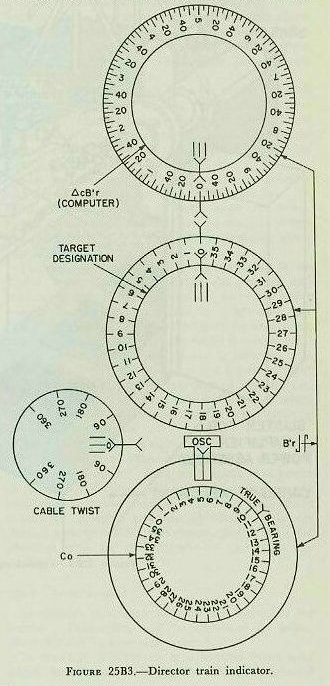
The train indicator is located on the optical shelf to the right of the trainer’s telescope. It receives ΔcB′r electrically from the computer, and director train (B′r) mechanically from the director. It has four dial groups arranged as shown in figure 25B3.
The upper group consists of an inner dial and a ring dial. The inner dial has only a pointer and is driven by ΔcB′r from the computer in such a way that one revolution of this dial is equal to 10° of ΔcB′r. The ring dial is driven by director train, with one revolution of the dial representing 10° of B′r. With the director in LOCAL or MANUAL, the trainer can follow the solution by matching the ring dial against the inner dial. If these two dials rotate together, the director is training at the same speed as the computed value.
The center group also consists of an inner dial and a ring dial. The ring dial shows actual director train with one revolution equal to 360° of B′r. This dial is graduated in 10° increments and is used in conjunction with the ring dial of the upper group. The inner dial has only a pointer, which is driven by a signal from some unit outside the director for target designation. The trainer picks up a designated target by matching the ring dial against the inner dial.
The bottom group has an inner dial and a ring dial. The ring dial is driven by director train, with one revolution equal to 360° of B′r. It has only a single pointer. The inner dial is driven by own-ship course (Co) from zero to 360 degrees and is graduated in 10° increments. By reading the ring pointer against the inner dial, true director bearing is determined. This is useful for locating a target whose true bearing has been supplied by an external source.
At the edge of the indicator face, halfway between the center and bottom groups, is a small dial for reading cable twist. The purpose of this dial is to show how far the director has trained in either direction from its neutral position. The dial shows how much farther the director can be trained before the 375° limit stops are reached.
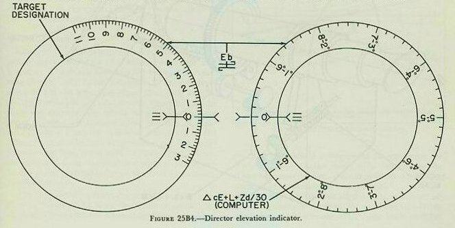
The elevation indicator is secured to the left of the pointer’s telescope and below it. This indicator has two dial groups arranged horizontally. It receives elevation correction (ΔcE + L + Zd/30) electrically from the computer, and director elevation (Eb) mechanically from the director (figure 25B4).
The left dial group has an inner dial and a ring dial. The ring dial is driven by Eb and is graduated in 2° increments from −30° to +110°. The inner dial has only a pointer, which is driven by some external unit for target designation.
The right-hand dial group also has an inner dial and a ring dial. The ring dial is driven by director elevation, with one revolution equal to 10° of Eb. The inner dial has only a pointer driven by elevation correction (ΔcE + L + Zd/30) from the computer. In LOCAL or MANUAL, the pointer can match these two dials and thus follow the computer solution, should he lose the target temporarily.
25B13. Elevation
As explained before, the description of director train in article 25B9 is generally true of director elevation. The telescope prisms rotate; the rangefinder rotates about its longitudinal axis; and the radar antenna rotates about its mounting as the pointer follows the target in elevation. In MANUAL the pointer’s handwheels are geared directly to the prisms, the rangefinder elevating arc, and the radar antenna elevating gearing. In LOCAL or AUTOMATIC, the electric motor of the power drive is connected and the handwheel connection broken. Then the handwheels are connected to a synchro control transformer in the elevation receiver-regulator. In AUTOMATIC, elevation is controlled by the algebraic sum of handwheel motion and elevation correction (ΔcE + L + Zd/30).
Director elevation (Eb) is the sum of target elevation and level angle: Eb = E + L. To hold the line of sight on the target automatically, changes in elevation due to relative target motion must be supplied in the form of increments of generated elevation (ΔcE). To hold the line of sight steady, changes in level must also be supplied. Therefore, continuous values of L are received from the stable element via the computer. In AUTOMATIC, since continuous values of level are received, the sights, rangefinder, and radar are said to be stabilized in level. In LOCAL or MANUAL, automatic stabilization in level is not possible. The elevation operator normally stays in AUTOMATIC when picking up or shifting targets, so as not to lose the advantage of the level input.
25B14. Crosslevel function
The third element of elevation correction, Zd/30, is called crosslevel function. Its purpose is to counteract an error caused by the telescope gearing. Figure 25B5 shows the operating principle of the telescopes. Prism rotation is caused by the input gear driven by the elevation drive. The input gear turns the floating gear, which is free to rotate and which acts as a spur gear. This floating gear drives another gear at the end of the worm shaft, turning the worm, which in turn elevates or depresses the prism.
When the telescope is stabilized in crosslevel (figure 25B6), Zd drives an input gear which drives the sector gear. Movement of the sector gear causes the telescope to rotate about its longitudinal axis, keeping the prism axis horizontal. However, the worm and its shaft move with the prism. This causes the gear at the end of the worm shaft to walk around the floating gear. Since the floating gear is meshed with the elevation-drive input gear, it cannot be rotated by the worm gear. Thus, the worm gear turns as it walks around the floating gear, introducing an undesired movement of the prism in elevation. Because of the gear ratio used, the error introduced is equal to Zd/30. To counteract the error, Zd/30 is introduced through the elevation input gear, and rotates the floating gear to eliminate the error as fast as crosslevel stabilization introduces it. Zd/30 does not exist as a separate quantity. The stable element generates the combined quantity L + Zd/30, which is sent to the computer. In the computer, ΔcE is added to form the complete elevation correction.
25B15. Crosslevel
Crosslevel stabilization is accomplished by a power drive, consisting of a receiver-regulator and a motor. The motor is connected to the telescopes, rangefinder, and radar antenna. The crosslevel drive rotates the telescopes about their long axes by an angle equal to Zd, as shown in figure 25B6. In a similar manner, the whole rangefinder and the radar antenna are rotated about the line of sight by Zd. As a result of crosslevel stabilization, the telescope crosshairs, the rangefinder, and the radar antenna are kept horizontal. Consequently, director elevation is measured in the vertical plane, not in the plane perpendicular to the deck as in main-battery directors.
The crosslevel receiver-regulator receives continuous values of Zd from the stable element. No method is provided for manual inputs of crosslevel except for a manual arrangement for returning the drive to zero. In the event of a casualty to the crosslevel power drive, the rangefinder and radar antenna are locked at zero crosslevel.
Limit switches are installed in the crosslevel receiver-regulator to protect the equipment. When the value of Zd reaches 17½°, the limit switches operate to stop the motor. When the value of Zd returns to less than 17½°, the motor cuts in again.
25B16. Range
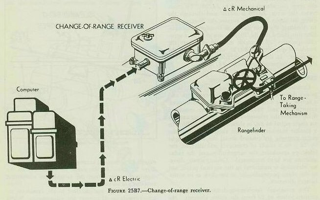
On the rangefinder beam in front of the rangefinder is a change-of-range receiver, shown in figure 25B7. It contains only a synchro receiver and a servo. Increments of generated range (ΔcR), called range correction, are received by the synchro from the computer. The servo drives the ΔcR signal into a differential in the rangefinder, where it is combined with motion of the rangefinder operator’s hand knob to produce an output which positions the rangefinder’s measuring wedges. In addition, the differential output positions synchro-transmitter rotors which transmit observed present range (R) to the computer.
The rangefinder operator uses his knob to bring the wander marks above the target. Then, if the computer solution is correct, ΔcR will keep the wander marks on the target, and the operator merely observes. If the solution is incorrect, the wander marks will drift away from the target, whereupon the operator turns his knob to bring the marks back on target. If either the change-of-range receiver or the ΔcR transmission fails, the operator must do the entire job of keeping the measuring wedges properly positioned. If the transmission of R fails, he must send the values of R to Plot by phone, to be set into the computer by hand.
In the center of the range knob is a button known as the rate control signal button. It is used in the same way as the rate control keys on the pointer’s and trainer’s handwheels. If the computer is set for automatic range rate control, the operator can rate control in range by pressing the button as he turns his knob.
25B17. Spotting
On the rangefinder beam in front of the rangefinder and to the left of the change-of-range receiver is a range-spot transmitter. This transmitter sends both individual and total spot values to the control officer’s spot transmitter, but sends only the total value of range spot to the computer. The instrument has one dial group, consisting of an inner dial and a ring dial. The ring dial indicates the value of each individual spot. This dial and its synchro are so geared that, when the spot knob is pushed in, the dial returns to zero. The inner dial shows the value of total range spot transmitted. The knob has 50-yard detents, so the operator can make spots by touch.
To the left of the control officer’s station is a spot transmitter. It has three dial groups arranged vertically, each with an inner dial and a ring dial. All three groups show the value of individual spots on the ring dial and the total spot on the inner dial. From top to bottom they show range, elevation, and deflection spots in that order. The elevation and deflection knobs have 1-mil detents so the control officer can spot by touch. Only total values of elevation and deflection spots are transmitted to the computer by this instrument.
25B18. Illumination control
Star-shell fire is controlled by a star-shell computer attached to the Mark 1A computer. Star-shell gun train, elevation, and fuze-setting orders are calculated by the star-shell computer and transmitted only to the guns firing star shells. Located at the illumination control officer’s station in the director is a star-shell spot transmitter. It functions in the same way as the control officer’s spot transmitter, except that the spots are star-shell range, elevation, and deflection spots. It has a range-spot knob as well as elevation-spot and deflection-spot knobs.
25B19. Multiple installations
On ships with only one director, the director roller path is the reference plane, and its axis of rotation determines the reference point in train. When more than one director is installed, all must transmit identical values of director train and director elevation for the same reference point. To this end, each director has a roller-path tilt corrector and a horizontal-parallax corrector.
The parallax corrector is in the train receiver-regulator. It receives unit parallax calculated in the computer for a 100-yard horizontal base length. In the receiver-regulator, the electrical signal from the computer is transformed to mechanical movement by a follow-up. Then a signal gear ratio converts unit parallax to the correct amount for the director’s actual distance from the reference point. This corrected parallax is fed to a mechanical differential. The other side of the differential receives actual director train. The output is director train corrected for horizontal parallax, which is the value of B′r that would be transmitted by a director actually at the reference point.
Should parallax transmission or the follow-up fail, manual application of parallax is possible. Two concentric parallax dials are located in the face of the train receiver-regulator. When the follow-up mechanism fails, a hand crank is used to match the zero on the ring dial against the pointer on the inner dial. This causes the correct parallax to be introduced. If parallax transmission fails, unit parallax can be received by phone and set on the outer dial against a fixed index.
The roller-path tilt corrector is located on the director carriage. Inclination of the director roller path from the reference plane is corrected in accordance with alignment data determined as described in chapter 21. Roller-path inclination in the sight plane is a function of the angle of director train from the high point. Director train B′r is a mechanical input to the tilt corrector. The train value of the high point and the inclination of that point are set on the mechanism after alignment has been checked. The output of the corrector is combined with director elevation above the roller path. The result is director elevation above the reference plane (Eb).
25B20. Radar
The Mark 25 radar is an automatic tracking fire control radar. Its antenna and parabolic reflector are mounted atop the director. Indicator scopes and other associated components are located in the director and below decks. This radar provides for three types of antenna scan: spiral for target acquisition, conical for tracking, and circle for spotting shell splashes in surface fire.
In normal operation, the automatic tracking feature relieves director personnel of making rate control corrections. Tracking signals — representing target range, bearing, and elevation — are generated from the radar information and compared with the generated range, bearing, and elevation from the computer. Any differences between the computer and radar quantities are transmitted to the director as corrections, to reposition it in accordance with the radar information.
The corrections, in turn, are transmitted to the computer, where they correct its solution until it matches the radar values. Once the target has been acquired by the radar, this process is continuous and automatic. Characteristics of the Mark 25 radar are described in Volume 3 of this course.
C. Computer
25C1. General
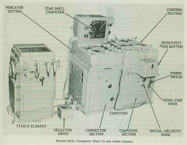
This section describes the Computer Mark 1A (figure 25C1). The Computer Mark 1A is the mechanical brain of the Gun Fire Control System Mark 37, which is used to control the fire of dual-purpose guns against both air and surface targets.
The Computer Mark 1A computes continuous gun orders containing corrections for all the significant factors affecting antiaircraft and surface fire. The corrections allow for motion of own ship and target during the time the projectile is in flight; for the curvature of the projectile path caused by gravity, drift, and wind; for pitch and roll of the ship; and for a number of other factors.
These gun orders, a fuze-setting order, and parallax corrections are continuously transmitted from the computer to the gun mounts. At the mounts, these orders are used to point the guns continuously, and to time the fuzes so that the projectiles will explode at the predicted position of the target.
Modifications of Computer Mark 1A have been developed to control the various calibers of dual-purpose guns in use in the Fleet. All modifications are essentially the same in appearance, function, and operation. They differ mainly with respect to the self-contained ballistic data which adapt them to a particular gun.
The Star-Shell Computer Mark 1, which is installed on top of the Computer Mark 1A as an integral part, also will be described in this section. In this text, when the main computer is referred to it is called merely the computer. The auxiliary instrument is always called the star-shell computer. Both instruments are shown in figure 25C2.

25C2. Functions
The computer functions are:
1. To permit the dual-purpose guns to be pointed and trained, and fuzes and sights to be set continuously for either AA or surface fire against a common target.
2. To aid the director crew in keeping the line of sight on target in either air or surface fire.
3. With the star-shell computer, to permit the dual-purpose battery to be pointed and trained, and fuzes to be set continuously for illumination of a surface target.
4. To permit, as an alternative to 1, control of the 40-mm or 3"/50 rapid-fire guns at short ranges, and the main battery in barrage fire against a common target.
The computer makes nearly all of the calculations required for control of the dual-purpose battery that can be computed centrally. This permits standardization of equipment and increases the flexibility in multiple installations. It also permits the Mark 37 system to be used on any type of ship large enough to support its weight.
25C3. Outputs
The computer calculates and transmits the quantities listed below. Some are for both single and multiple installations, while some are for multiple installations only. Pv is used only on large carriers of the Essex and Midway types. Figure 25A3 shows graphically the distribution of most of the outputs. These outputs are supplied as follows:
Electrically to guns:
1. B′gr — Gun train order (automatic and indicating).
2. E′g — Gun elevation order (automatic and indicating).
3. Ph — Train parallax for a 100-yard horizontal base.
4. Pv — Elevation parallax for a 100-yard horizontal base.
5. F — Fuze-setting order for mechanical fuzes.
6. Ds — Sight deflection.
7. Vs — Sight angle.
Electrically to director:
1. ΔcB′r — Bearing correction (automatic and indicating).
2. ΔcE + L + Zd/30 — Elevation correction (automatic and indicating).
3. ΔcR — Range correction.
4. Ph — Train parallax for a 100-yard horizontal base (multiple installations only).
Mechanically to the star-shell computer:
1. B′gr — Gun train order.
2. E′g — Gun elevation order.
3. R2 — Advance range.
4. WrD + KRdBs — Star-shell deflection rate.
Mechanically to the stable element:
1. B′r — Director train.
In the list above, where the same signal is transmitted both in automatic and in indicating, the signal is identical. It is sent over separate circuits following different paths to separate synchro receivers at the directors or mounts. This feature enables one transmission line to be used if the other is damaged. One controls the power drive and the other moves indicator dials. Use of the circuits can be exchanged, should the need arise, by suitable switching arrangements at the fire control switchboard.
Elevation parallax for a vertical base (Pe) is included in sight angle (Vs), and therefore in gun elevation order (E′g). It does not exist as a separate quantity.
25C4. Inputs
The computer receives the following inputs from the sources and by the methods indicated:
Mechanically from stable element: L — Level (or Lj, selected level); Zd — Crosslevel (or Zdj, selected crosslevel); L + Zd/30 — Level plus crosslevel function.
Electrically from director: Eb — Director elevation; B′r — Director train; R — Observed present range (may be received by phone); Dj — Deflection spot (may be received by phone); Vj — Elevation spot (may be received by phone); Rj — Range spot (may be received by phone); and rate control or on-target signals for range, elevation, and bearing.
Electrically from gyro compass and pitometer log: Co — Own-ship course; So — Own-ship speed.
By phone from director, put in manually: A — Target angle (initial or corrective value); Sh — Target’s horizontal speed (initial or corrective value); dH — Rate of climb (initial or corrective value).
Manually — calculated or estimated in plotting room: rate control values for range (as an alternative to the director signal); dR — Direct range rate (target diving speed); Bw — True direction of true wind; Sw — True wind speed; jBr — Initial relative target bearing; jE — Initial target elevation; jR — Initial range; I.V. — Initial velocity; Tg — Dead time; and dip angle (by setting R2).
25C5. Principles
A detailed discussion of the principles of basic mechanisms used in mechanical computers has been given in section E of chapter 19. The present section provides a brief description of the calculations made within the computer.
The computer solution of the AA problem is in many respects similar to the solution of the surface problem by the rangekeeper described in chapter 19. The computer computes relative target motion rates which are used in generating cR, cBr, and cE. The effects of changes in Co are taken into account in the case of cBr. Since the computer was developed before radar became reliable, it was designed for rangefinder ranges. Because rangefinder ranges are somewhat erratic at best, the computer used generated range (cR) for its calculations. This improves the smoothness of operation of the instrument. Measured relative target bearing (Br) and target elevation (E) are used for computations, because they can be measured accurately and smoothly. The target elevation (E) is obtained by subtracting level (L) from director elevation (Eb): E = Eb − L. Relative target bearing (Br) is obtained by adding deck-tilt correction (jB′r) to director train (B′r): Br = jB′r + B′r.
Also, in keeping with methods used in the surface rangekeeper, the computer generates increments of range, relative bearing, and elevation (ΔcR, ΔcB′r, and ΔcE). ΔcB′r is sent to the director train receiver-regulator to move the line of sight according to the generated value of director train. It takes into account both deck-tilt correction and changes of own ship course. Thus, if the solution is correct, ΔcB′r will keep the line of sight on the target in train while the ship rolls, pitches, and changes course. As explained in article 25B9, this is only when the director train power drive is in automatic. ΔcB′r, when used as described above, is called bearing correction. ΔcE is added in the computer to level correction (L) and crosslevel function (Zd/30). The sum (ΔcE + L + Zd/30) is called elevation correction. It is sent to the director elevation receiver-regulator to hold the line of sight on target in elevation. This it will do only if the director elevation power drive is in automatic and if the computer solution is correct.
These changes in director train and elevation caused by bearing and elevation corrections show up in new values of director train (B′r) and director elevation (Eb). Thus there is a continuous feedback into the computer, since the director transmits B′r and Eb continuously to the computer. In other words, the computer and director together form a regenerative group. This allows the director to follow an obscured target by riding the computer solution. As long as the solution is correct, the director will remain on the target. This regenerative arrangement also permits indirect fire against a temporarily obscured target. This is accomplished in a manner similar to that described in chapter 19 for a surface rangekeeper. In addition, the computer is so arranged that generated bearing (cBr) can be used for calculations in surface fire. When this arrangement is used, the computer is regenerative in bearing within itself and can control indirect fire without director inputs.
Ballistics, too, are computed in the same manner in the computer as they are in the surface rangekeeper. That is, the three linear rates (dR, RdE, and RdBs), generated present range (cR), and certain other necessary quantities are used. Actually, the computer develops advance range (R2) and predicted target elevation (E2) by a series of approximations. Using the advance target position, computations of ballistics are essentially the same as those developed in section 24B.
Because approximations are used in the computer, certain variations from the analytical solution exist. Some of these are:
1. Wind computations are empirical equations, based on an approximation of the line of fire.
2. Air-density corrections are separately computed, and applied to the computer as a change in initial velocity.
While the standard new-gun initial velocity for the 5"/38 gun is 2,600 foot-seconds, the computer calculations are based on an I.V. of 2,550 foot-seconds. This reduces the size of the maximum corrections which may have to be applied, and thus increases the accuracy of the average correction. Corrections may be automatically calculated for any variation of initial velocity between the standard (2,600 fs) and the lower limit (2,350 fs) which is set into the computer.
The elements considered in the computation of sight angle, sight deflection, and fuze-setting are:
Vs — Sight angle: Vt (elevation prediction), Vf (superelevation), Vw (wind elevation correction), Vfm (initial velocity elevation correction), Vx (complementary error), Pe (elevation parallax correction for a 30-foot vertical base), and Vj (elevation spot).
Ds — Sight deflection: Dt (deflection prediction), Dfs (drift), Dw (wind deflection correction), and Dj (deflection spot).
F — Fuze setting: Tf (time of flight) and Tg (dead time).
The basic gun train and elevation orders have been discussed in chapter 24. Briefly, gun train order (B′gr) is equal to director train (B′r) plus deck deflection (Dd): B′gr = B′r + Dd. Deck deflection is equal to partial deck deflection (jDd) and trunnion-tilt train correction (Dz): Dd = jDd + Dz. Gun elevation order (E′g) is equal to director elevation (Eb) plus sight angle (Vs) minus trunnion-tilt correction in elevation (Vz): E′g = Eb + Vs − Vz. B′gr is corrected for horizontal parallax (Ph) at the gun, while E′g, as transmitted by the computer, includes the correction for vertical parallax (Pe). On large carriers, E′g is further corrected at the guns for vertical parallax caused by horizontal displacement (Pv).
25C6. Rate control
1. General. As previously explained, the computer determines the relative motion rates (dR, RdE, and RdBs) from the primary data indicated below:
a. Estimated or computed: target angle (A), target horizontal speed (Sh) and rate of climb (dH).
b. Measured: present range (R), relative target bearing (Br), target elevation (E), own-ship speed (So), own-ship course (Co), and time (T).
From these relative motion rates, generated target position is computed (cR, cBr, and cE). Since the relative motion rates as well as the generated value of range (cR) are used in the calculations for ballistics and predictions, it is necessary that these values be accurate for gun orders to be correct.
If the primary data listed above are correct, the relative motion rates will be correct and the generated target position values (cR, cBr, and cE) will agree with the observed target position values (R, Br, and E). If the primary data are not correct, however, the relative motion rates will be incorrect, and the generated target position values will not agree with the observed target position values; consequently gun ballistics and predictions and, therefore, gun orders will be in error.
Since the measured quantities of the primary data are determined by instruments, their accuracy is relatively high; consequently, whenever there is disagreement between generated and observed values of present target position, the likeliest source of error is in the quantities A, Sh, and dH. By adjusting the quantities A, Sh, and dH, the relative motion rates (dR, RdE, and RdBs) can be corrected, bringing cR, cBr, and cE into agreement with R, Br, and E. The method by which this is accomplished is known as rate control.
It is a simple matter to arrange a set of dials that will indicate disagreement between the actual and computed values of range, bearing, and elevation. For example, consider target elevation, and assume a dial group like that in figure 25C3. The outer ring dial is driven by measured or actual target elevation (E). The computer, receiving director elevation (Eb) from the director, combines Eb with level angle (L) in a differential to produce target elevation, one use of which is to drive the observed elevation dial. The inner dial is driven by generated target elevation (cE) as determined by the computer.
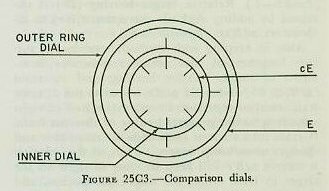
As the director LOS follows the target, changes in target elevation will obviously cause the outer ring dial to rotate. The speed of rotation will be proportional to the actual elevation rate. Changes in generated elevation drive in the inner dial at a speed proportional to the computed elevation rate (RdE). Equal rotational speeds of the outer ring dial and the inner dial are apparent when the inner dial marks remain stationary with respect to the outer ring dial marks. This condition signifies that the computed elevation rate equals the actual elevation rate. When the dials turn at different speeds, the computed rate (RdE) is evidently wrong and must be corrected by correcting the quantities A, Sh, and dH. This same process can be applied to compare the computed and actual range and bearing rates.
Rate controlling can be accomplished with the director in automatic, local, or manual drive operation. Since operation of the director in automatic provides optimum use of the rate control features of the Computer Mark 1A, the ensuing discussion will consider the rate control features of the director with its power drives in automatic.
In this condition, ΔcR, ΔcB′r, and ΔcE + L + Zd/30 will keep the director automatically on the target without handwheel motion by the pointer and trainer as long as the solution remains correct. Also, the rangefinder wander marks will keep on the target and the radar target pip will remain in the range notch.
If the solution is not correct, it is necessary for the director pointer and trainer to use their handwheels, with their rate control key depressed, to keep the LOS on the target. If the LOS gets off the target, the rate control keys should be released, and should not be closed until the crosswires are back on target. Rate control keys should be closed only when the crosswires are on target. Similarly, if the solution is not correct, the rangefinder operator and radar operator will have to use their range controls to keep the wander mark on target and the pip in the notch. While on target in range, the rate control keys should be depressed. However, if the operators get off in range, the rate control keys should be released until the operators get back on target.
2. Rate control symbols. In addition to the symbols previously covered in the course, the following symbols are used in the analysis of rate control:
jBr — Angular bearing rate correction.
jE — Angular elevation rate correction.
jdR — Direct range rate correction.
These values represent the angular differences between the generated and observed changes in bearing and elevation and the linear difference between generated and observed range, and they are used in the rate control mechanism to correct the quantities A, Sh, and dH. When jBr and jE are multiplied by a value of range (as will be explained later) they provide the linear bearing and elevation rate corrections applied to the rate control mechanism:
jBc — Linear bearing rate correction. The rate correction primarily affecting linear deflection rate (RdBs).
jEc — Linear elevation rate correction. The rate correction primarily affecting linear elevation rate (RdE).
As will be explained in article 25C7, jdR in the slant plane is converted to the horizontal plane, resulting in the following quantity:
jdRh — Horizontal range rate correction. The rate correction primarily affecting horizontal range rate.
The following symbols will be used to represent the final rate control mechanism corrections to A, Sh, and dH: jSh (target horizontal speed correction), jHc (rate-of-climb correction), jCt (target angle/course correction), and jRc (linear range correction).
3. Methods of rate control. In the Computer Mark 1A, provision is made for two methods of rate control. These are automatic and manual rate control. Automatic rate control is made possible by the inclusion of a rate control computing mechanism in the computer. When employed, this mechanism will compute and correct the target motion rates A, Sh, and dH for targets at speeds of 15 knots to 800 knots. The rate control mechanism is not designed to operate accurately below target speeds of 15 knots; hence for the lower-speed targets, manual rate control should be employed.
Selection of the method of rate control is made at the computer by positioning the control switch and the range rate control switch. The control switch governs the method of bearing and elevation rate control. The range rate control switch governs the method of range rate control.
a. Automatic rate control. Automatic rate control is the normal method of operating Computer Mark 1A for all air targets and for surface targets at speeds of 15 knots and over.
In automatic rate control, follow-up motors in range, bearing, and elevation are employed to keep the generated dials continuously rotating at the same rate as the observed dials. Figure 25C4 shows the flow diagram for bearing and elevation. Br and E are obtained from inputs of director train and elevation (Br = B′r + jB′r and E = Eb − L). ΔcBr and ΔcE are obtained from the computer tracking section [ΔcE = ΔT(dE)].
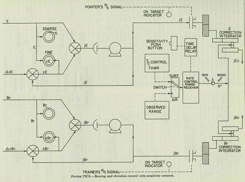
The generated and observed values of bearing and elevation are compared in a differential, the output of which is used to close the contacts on the follow-up motors. The output of these follow-up motors, as well as the increments of generated bearing and elevation, is used to drive the generated dials. When the generated value equals the observed value, the output of the differential will be zero, the contacts to the follow-up motor will open, and the follow-up motor will stop driving the generated dials. If the computed rates, dBr and dE, are correct, cBr and cE will keep the generated dials changing at the same rate as the observed dials. Any error in the computed rates, however, will cause the follow-up motors to drive to keep the generated dials rotating at the same rate as the observed dials.
A range follow-up motor is employed to drive the generated range dial into agreement with the observed range dials, although, as will be explained later, the method of accomplishing this varies from that employed with bearing and elevation.
When the director operators close the rate control keys, the signal not only is transmitted to the computer ON TARGET indicators, but also is used to close clutches between the output shafting of the follow-up motors and the input shafting to the rate control mechanism. The jBr clutch and jE clutch are shown on figure 25C4. Thus when the director rate control keys are closed and an error exists in the computed rates (dR, dBr and dE), the output of the follow-up motors will drive into the rate control mechanism.
In this manner, when an error exists, the rate control mechanism automatically receives the rate corrections jdR, jBr, and jE, the differences between the rates of change of generated and observed range, bearing, and elevation. The rate control mechanism then will correct the values of A, Sh, and dH, thereby causing the computer to compute new target motion rates (dR, dBr, and dE). The new target motion rates will result in new values of ΔcBr and ΔcE to drive the generated dials. In addition, since target motion rates are used in the computer prediction and correction sections, the computer will compute new and more accurate gun orders.
b. Manual rate control. Manual rate control must be used when the rate control mechanism is inoperative, for indirect fire when observation of the target is impossible, and for surface targets below a speed of 15 knots. In this method, initial values of target angle, target horizontal speed, and target rate of climb must be estimated and set manually into the computer. When the director rate control keys are closed, signals appear at the computer ON TARGET indicators. Computer personnel then know that the director is on target and the correct values of R, Br, and E are indicated on the comparison dials. If the generated dials are not rotated at the same speed as the observed dials, the initial estimates of A, Sh, and dH were incorrect, and are changed manually until all comparison dials are rotating together. In addition, the computer range operator must ensure that the correct value of range is continuously set on the range dials.
It should be evident that initial estimates of A, Sh, and dH depend upon the skill of the control officer. Even the most experienced officers cannot estimate these values within close enough limits to ensure accuracy of the solution; consequently a correct solution generally requires changing manually the initially estimated values. For this reason, and because of the short duration of the air problem, manual rate control is considered an auxiliary type of operation for air targets.
25C7. Rate control mechanism
1. Analytical solution. The function of the rate control mechanism is to correct the values A, Sh, and dH. By analyzing the differences between changes in generated and observed values of range, bearing, and elevation (jdR, jBr, and jE), this mechanism determines what errors in A, Sh, and dH were responsible for such differences, and corrects the errors. Once A, Sh, and dH are corrected, the computed relative motion rates should be correct and, therefore, the gun orders should be accurate.
Figures 25C5 and 25C6 show analytically and by flow diagram how the rate control mechanism solves the problem. Since the basic mechanisms employed in the rate control mechanism require linear inputs, the angular bearing and elevation rate corrections (jBr and jE) must be converted into linear bearing and elevation rate corrections (jBc and jEc). As shown in figure 25C5, the linear rate corrections in the vertical plane through the line of sight (jEc and jdR) are resolved into horizontal and vertical components. The horizontal components are combined to produce horizontal range rate correction (jdRh). The vertical components are combined to produce rate-of-climb correction (jHc). The latter correction, jHc, is used to correct target rate of climb (dH).
jHc = jEc cos E + jdR sin E


The horizontal range rate correction (jdRh) and the linear bearing rate correction (jBc), both of which lie in the horizontal plane, are resolved into components in and perpendicular to the target vector as shown in the figure. The components which lie in the target vector are combined to produce target horizontal speed correction (jSh). The components perpendicular to the target vector are combined to produce target course correction (jCt). These values are used to correct target horizontal speed (Sh) and target angle (A) or target course (Ct).
jCt = jdRh sin A + jBc cos A
2. Basic mechanisms employed. The basic mechanisms employed to resolve the rate corrections as explained above are four component integrators. These mechanisms perform the same functions as component solvers. The differences in construction, however, enable the component integrator to handle rapidly changing inputs throughout an unlimited range of values, whereas the component solver is limited in the range of the inputs it can handle.
The inputs of the component integrator, a changing angular value and a changing linear value, establish a vector which has length and direction. As shown in figure 25C6, the angular input to the elevation component integrators is target elevation (E), and the angular input to the target angle component integrators is target angle (A). Since the second input to each must be linear, bearing and elevation correction integrators (disc type) are employed to convert the angular rate corrections (jE and jBr) into linear rate corrections (jEc and jBc). The correction integrators have a further function in controlling computer sensitivity, which will be discussed later. Note in the figure that two of the outputs of the jdR and jEc component integrators are combined to produce jdRh, the linear input to the jdRh component integrator.
These integrators continuously resolve the changing vector into sine and cosine functions of the vector input. The sine and cosine functions are combined into the required corrections, jCt, jSh, and jHc, as indicated in the figure. As previously stated, when A, Sh, and dH are corrected, new values of dR, RdE, and RdBs are computed which give more accurate gun orders.
25C8. Computer sensitivity
The rate control system of Computer Mark 1A includes sensitivity units which control the time required by the computer to reduce errors in generated rates to the point where the corrected rates are sufficiently accurate to compute adequate gun orders. Sensitivity may be thought of as the speed with which the errors are corrected by the rate control mechanism. If the errors are corrected within a relatively short time interval, the sensitivity is considered to be high, and if the errors are corrected within a relatively long time interval, the sensitivity is considered to be low.
The time interval used is called the time constant (Tc), and is defined as the time in seconds required to reduce a rate error to an acceptable figure, or 37% of its initial value. Thus a low time constant will give high sensitivity, and a high time constant will give a low sensitivity. For example, assume a direct range rate error (jdR) of 100 yd/sec, and accurate ranging by the rangefinder or radar operator. If the Tc is 2 seconds, the 100 yd/sec error would be reduced to a 37 yd/sec error in 2 seconds, and the sensitivity of the range rate network would be considered high. In the next 2 seconds, the 37 yd/sec error would be reduced further to approximately a 14 yd/sec error (37% × 37).
If the Tc is 16 seconds, the 100 yd/sec error would be reduced to a 37 yd/sec error in 16 seconds, and the sensitivity of the network would be considered low. In the next 16 seconds, the 37 yd/sec error would be reduced further to approximately 14 yd/sec error (37% × 37). Thus the time constant can be used as an indication of the system sensitivity, or the speed with which it arrives at a solution accurate enough to compute adequate gun orders.
High sensitivity is desirable in a computer so that large rate errors may be corrected rapidly, as when first acquiring a target or when the target maneuvers radically. On the other hand, too high a sensitivity results in instability in computer operation; if the rate of correction of a given rate error is too high, momentary overcorrection of the error results, and oscillation of computer solution is encountered. Furthermore, at long ranges particularly, the rate errors detected may be in large part due to tracking errors. To use too large a rate correction in this case would result in correcting the problem for an error that does not exist; again, unsatisfactory results would be obtained. Consequently, the sensitivity networks are designed with two points in mind: (1) the rate control mechanisms use, as inputs, values of jEc, jBc, and jdR that are something less than the actually detected rate errors; and (2) provision is made in the mechanism design for varying the ratio of the rate error used to that of the rate error detected, so that the time constant, or sensitivity, is variable and adjustable (within limits).
Functionally, the sensitivity network of Computer Mark 1A is composed of two separate parts: (1) control of the sensitivity of the range rate control network and (2) control of the sensitivity of the bearing and elevation rate control network.
25C9. Range rate control network
1. General. Control of the sensitivity of the range rate control network enables the computer range operator to use large direct range rate corrections (jdR) when the range rate errors are large, and small direct range rate corrections (jdR) when the range rate errors are small, by varying the time constant of the network and hence the sensitivity. Before discussing how this is accomplished, however, it is necessary to understand the operation of the network. Figure 25C7 shows the units employed in the range rate control network.
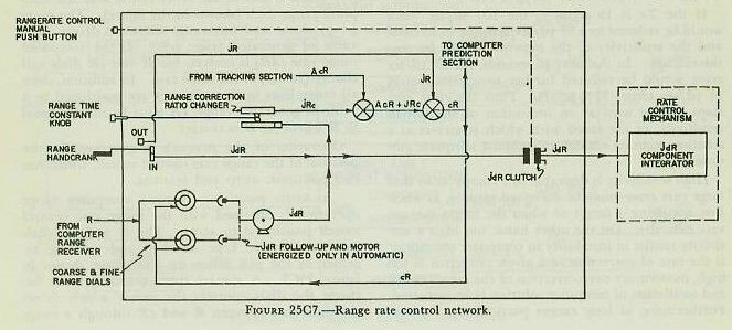
2. Operation. The director transmits to the computer range receiver a value of observed range (R) which is sent to the inner coarse and fine computer range dials (shown in the figure). The outer (ring) coarse and fine range dials are driven by a value of generated range (cR). If the computed range rate (dR) is correct, the R and cR dials will change (rotate) at the same rate. In addition, since all range lines in the computer are positioned by a value of generated range, cR must be exactly equal to R whenever R is correct.
Operation of the network is governed by the position of the range rate control switch, which has two positions: AUTO and MANUAL.
a. AUTO position. Normal computer range operation is obtained with the range rate control switch positioned to AUTO. The R and cR dials continuously are kept matched and rotating together by the jdR follow-up and motor shown in figure 25C7. A special contact arrangement between the dials controls the motor which drives the difference between R and cR through a range correction ratio changer into the cR line. The linear correction to cR, shown in the figure, is called linear range correction, jRc. Whenever either the director rangefinder operator or the radar range operator depresses his director rate control button, the jdR clutch is energized (closed), and a value proportional to the difference between R and cR is also driven into the rate control mechanism as direct range rate correction, jdR.
b. MANUAL position. Whenever the range rate control switch is positioned to MANUAL, the computer range operator must perform the function of the jdR follow-up motor by rotating the range handcrank. With the range handcrank in the OUT position, the computer range operator matches the generated range dials with the observed range dials. In so doing, he introduces initial range (jR) into the computer. If the computer has been tracking a target, the tracking section has developed increments of generated range (ΔcR), which are combined with jR to produce generated range (cR). As shown in the figure, cR is used both in the computer prediction section and to position the cR dials. With the range handcrank at the IN position, the computer range operator can still match the generated range dials with the observed range dials, though at a much slower rate, since the input must pass through the range correction ratio changer. As shown in figure 25C7, whenever the computer range operator rotates the range handcrank in the IN position to keep the cR dial rotating at the same rate as the R dial, and at the same time pushes the computer range rate control manual push button, the jdR clutch is energized (closed), and a value proportional to the difference between R and cR is driven into the rate control mechanism as jdR.
3. Sensitivity control. The range correction ratio changer is a disc-type integrator whose function is to control the amount of direct range rate correction (jdR) going into the rate control mechanism for any given amount of linear range correction (jRc). The disc of the mechanism is turned by direct range rate correction (jdR). The carriage is positioned directly by the range time constant knob on the front of the computer. The roller drives linear range correction (jRc) into the cR line.
It should be remembered that the output of a disc-type integrator depends both on the input to the disc and on the position of the integrator carriage on the disc. With the carriage near the center of the disc, the roller output will be minimum. With the carriage at the periphery (edge) of the disc, the roller output will be maximum.
A sleeve on the range time constant knob is graduated from 0 to 16 seconds. As previously stated, the time constant represents the time in seconds required to reduce a given rate error to 37% of its initial value, and is a measure of the sensitivity of the network. The setting on the RTC knob determines the amount of direct range rate correction (jdR) introduced into the rate control mechanism for each unit of linear range correction (jRc) applied to generated range (cR).
Suppose generated range (cR) needs a correction (jRc) which requires ten turns of the integrator roller. If the range time constant knob is at the 1-second position, the integrator carriage is positioned near the center of the disc; hence relatively many turns of the disc (by the input jdR) are needed to turn the integrator roller the ten revolutions to produce the required amount of jRc. A relatively large jdR, therefore, is applied to the rate control mechanism (if the jdR clutch is energized) for the jRc needed to match the range dials.
If the range time constant knob is at the 16-second position, the integrator carriage is positioned near the periphery (edge) of the disc; hence relatively few turns of the disc (by the input jdR) are needed to turn the integrator roller the ten revolutions to produce the required amount of jRc. A relatively small jdR, therefore, is applied to the rate control mechanism (if the jdR clutch is energized) for the jRc needed to match the range dials.
By positioning the range time constant knob, the computer range operator controls the sensitivity of the range rate control network. By selecting a small RTC setting, a large value of jdR can be applied to the rate control mechanism. By selecting a large RTC setting, a small value of jdR can be applied to the rate control mechanism. In practice, the computer range operator should keep the setting of the range time constant knob as low as possible without causing instability in the computer solution.
25C10. Bearing and elevation rate control network
1. General. Figure 25C8 shows the units employed to control the sensitivity of the bearing and elevation rate control network. As shown in the figure, the function of the network is to convert the angular bearing and elevation rate corrections (jBr and jE) into linear bearing and elevation rate corrections (jBc and jEc). These linear corrections are applied to the component integrators of the rate control mechanism as explained in paragraph 25C7. The sensitivity of the network is controlled: (a) by network design to cause the magnitude of the linear output to vary with a value of range; and (b) by operation of the sensitivity push button.

The value of the time constant (Tc) in seconds for the network is expressed by the equation Tc = 2 × R/R′. The constant 2 represents the basic time constant established by the change gears. As shown in figure 25C8, the change gears (labeled Ke and Kb) reduce the value of the angular rate corrections (jBr and jE) applied to the correction integrator. This reduction is reflected in the magnitude of the integrator outputs (jBc and jEc), and hence affects the sensitivity of the network at all ranges.
It is necessary to reduce the measured angular rate corrections (jBr and jE) applied to the network in order to prevent overcorrection of the solution by the rate control mechanism due to the tracking errors. Whenever the rate control mechanism is employed, the amount of handwheel motion by the director pointer and trainer in staying on target determines the magnitude of the angular rate corrections (jBr and jE). The handwheel motions contain tracking errors due to inaccurate tracking of the target in bearing and elevation, lost motion in the mechanical parts of the system, and maladjustment of the power drives and radar. By employing change gears, the effect of the tracking errors in overcorrecting the solution is reduced. Normally the change gears installed give the network a basic time constant of two seconds.
The bearing and elevation correction integrators are employed to multiply the angular corrections (jBr and jE) by a value of range (which is limited from 500 yards to 8,000 yards by the limit stop shown in figure 25C8). Thus the angular rate corrections are converted into linear rate corrections (jBc and jEc) required by the component integrators of the rate control mechanism. The value of range called rate control range (R′) positions each correction integrator carriage near the center of the disc for ranges of 500 yards, and near the periphery (edge) of the disc for ranges of 8,000 yards. In the former case (R′ = 500 yd), the output of each integrator will be minimum, and in the latter case (R′ = 8,000 yd), the output of each integrator will be maximum.
2. Air targets. For operation against air targets, the AIR-SURFACE switch is positioned at AIR. The range input from the rangefinder or radar activates the rate control range receiver shown in figure 25C8. In the latter unit, a single-speed synchro motor is used to receive the input value of observed range and to close contacts on a servo motor. This causes the value of range to drive through the limit stop to position the correction integrator carriages.
When observed range is between 500 yards and 8,000 yards, the limit stop will not function and the value of observed range will be equal to the value of rate control range (R = R′). Thus, since the ratio of R/R′ is unity, the time constant for the network becomes equal to the basic time constant, or 2 seconds.
When the observed range equals or exceeds 8,000 yards, the limit stop functions, and the value of rate control range (R′) applied to the two correction integrator carriages remains at 8,000 yards. Therefore, for all air targets at a range of 8,000 yards and beyond, the value of the linear rate corrections (jBc and jEc) applied to the component integrators is a maximum. As can be determined from the time constant equation (Tc = 2 × R/R′), the time constant will increase uniformly as the range increases beyond 8,000 yards; hence the network sensitivity will commence to decrease uniformly beyond that range.
Figure 25C9 will clarify the preceding discussion. The figure assumes a target at 8,000 yards (position 1) and a target at twice the range, or 16,000 yards (position 2). The effect of the change gears in reducing the value of jE applied to the elevation correction integrator will be represented by a constant gear ratio, Q. The output of the elevation correction integrator for target position 1 is the correct linear equivalent of jE, since jEc1 = Q × R′ × jE and R = R′. Furthermore, this represents the maximum output of the correction integrator, since R′ is limited to 8,000 yards by the limit stop. But at position 2, the correct linear equivalent of jE is jEc2, obtained by multiplying the product (Q × jE) by a range of 16,000 yards (jEc2 = Q × jE × 16,000).

Since by design of the network jEc1 is applied to the component integrators at all ranges of 8,000 yards and beyond, it will take a longer time for the rate control mechanism to reduce the given angular rate error for a target at position 2 than at position 1. Note that for the ranges given in the figure jEc2 = 2 × jEc1, and that the range at position 2 is twice the range at position 1. Since at position 2 only one half of the correct linear rate correction is being applied to the component integrators, it will take twice as long for the rate control mechanism to remove the entire jE correction for a target at position 2 as at position 1. This can be substantiated further by substituting the correct values of range in the network time constant equation (Tc = 2 × R/R′):

For air targets below ranges of 8,000 yards, it may be necessary to lower the network time constant (increase the sensitivity) momentarily in order rapidly to remove large rate errors such as those caused by a radically maneuvering target. To enable the computer operator to lower the time constant temporarily, the sensitivity push button and the time delay relay (see fig. 25C8) are provided. Pressing the sensitivity push button causes the range servo motor of the rate control range receiver to drive to its upper limit (8,000-yard position). After the sensitivity push button is released, the time delay relay maintains this position for a predetermined period, usually about 2 seconds. For example, if a target is at a range of 5,000 yards, the network time constant is:

Thus the rate error will be reduced to 37% of its initial value in 1.25 seconds instead of 2 seconds.
3. Surface targets. For surface targets, the AIR-SURFACE switch is positioned at SURFACE. When so positioned, it disconnects the rate control range receiver from the rangefinder or radar, and connects it to the time constant control transmitter. The latter unit is a synchro transmitter used to transmit a predetermined value of range to the rate control range receiver. This value is usually set at 3,000 yards, since experience has proved that the system operates best at this range for surface targets. Thus, as determined by the time constant equation, the time constant will increase uniformly at all ranges for surface targets, since R′ is always 3,000 yards, unless the sensitivity push button is pressed.
In the latter case, R′ becomes 8,000 yards for approximately two seconds, as explained above. For the surface problem, pressing the sensitivity push button will reduce the time constant at all ranges, and hence increase the network sensitivity. The following examples will illustrate how the time constant is affected by the sensitivity push button for the surface problem. If the observed range is 8,000 yards, the time constant is:
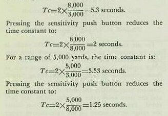
25C11. General description
Computer Mark 1A is built in four sections for ease of handling and assembling. These are: control section, indicator section, computer section, and corrector section. The first two are mounted on top of the second two in the order given. Figure 25C2 shows these four sections. The side nearest the stable element is the rear of the computer.
The control section contains the mechanisms for computing and controlling rates, and carries most of the knobs, cranks, and dials. The computer section (below the control section) contains the mechanisms that calculate the ballistics. The indicator section shows on dials and counters the end results of the ballistic calculations: sight angle (Vs), sight deflection (Ds), fuze order (F), and advance range (R2). Below the indicator unit, the corrector unit computes and indicates gun train order, gun elevation order, and parallaxes. Figure 25C1 shows many of these items, plus additional ones, some of which will be discussed later. Frequent reference to this figure in the following discussion will help the student to grasp the overall picture of the computer.
Many of the knobs and cranks have more than one position. Locking pins are provided to hold the cranks in the position desired. Some knobs have crank handles attached to permit rapid turning.
25C12. Target and own-ship dial group
Refer to figure 25C10 when studying this article. This group is located on the control unit at the rear center (see fig. 25C1). The directions of wind, own-ship, and target motions and the speeds of wind and own ship are indicated. Inscribed on the target dial, at the rear, are the outline of a plane and a compass rose. The own-ship dial group, at the front, has three concentric dials. On the inner dial are inscribed the outline of a ship and a compass rose. The intermediate ring dial has only a compass rose, while the outer ring dial has only an index mark. Between the target dial and the own-ship dial group is a pair of fixed indexes (in line with one another) representing the horizontal projection of the line of sight.
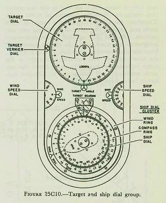
The target dial indicates only target angle (A) against the fixed index. The inner or ship dial of the front group reads relative target bearing (Br) against the fixed index. On the compass ring of the intermediate ring dial, own ship’s course (Co) is read against the bow of the ship outline of the inner dial. Also on the intermediate ring, true bearing (B) is read against the fixed index. The value of true direction of true wind (Bw) is determined by reading the intermediate-dial compass rose against the index of the outer ring. The student is reminded that Bw is the direction from which the true wind is blowing.
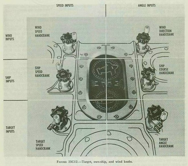
Normally Co and So are received by synchro transmission from the gyro compass and the pitometer log respectively. Own ship’s speed is indicated in knots on a dial to the right of and between the target dial and own-ship dial group. Both Co and So can be put in manually by the own-ship course knob and own-ship speed knob respectively. These knobs have two positions, IN and OUT. In the OUT position, the values of Co and So are received electrically, while, with the knobs IN, Co and So must be introduced into the computer manually.
Bw and Sw are introduced manually by knob only. The instrument continuously computes wind angle between the wind direction and the line of fire. Thus the setting of Bw is changed only when the wind direction changes. See figure 25C12.
Introducing target angle (A) into the computer enables the computer to solve for the value of true target course (Ct). This true course will be corrected continuously as in the surface rangekeeper. Target angle can be introduced into the computer automatically or manually.
In normal computer operation (automatic rate control), A is slewed to the proper 90-degree quadrant when the computer time motor is started; thereafter the exact value of A is determined and kept corrected by the rate control mechanism.
In manual computer operation (manual rate control), A is estimated by the director crew, phoned to the plotting room, and introduced manually into the computer; thereafter A is changed as necessary to obtain a correct solution.
The target angle (A) knob has attached to it a two-position shift lever labeled HAND and AUTO. To introduce A into the computer manually, the shift lever must be thrown to HAND. To permit changes of A by the rate control mechanism, the shift lever must be thrown to AUTO. In addition, for the rate control mechanism to function, similar levers on the target-speed (Sh) knob and rate-of-climb (dH) knob must be thrown to AUTO.
25C13. Target-speed and time dial group
This group, under a single round window, is located at the right front of the control unit (fig. 25C2). Displayed are: dH in knots on a dial, Sh in knots on a counter, target-speed diving in knots on a dial, and time on two dials (fig. 25C11).

The rate-of-climb (dH) dial is at the right rear of the group. dH can be introduced manually, but normally is controlled by the rate control mechanism as described in article 25C7. The dH knob shift lever is thrown to HAND for manual operation and to AUTO for control of dH by the rate control mechanism.
At the left front of the window is the Sh counter which shows horizontal ground speed of the target in knots, from 0 to 800 knots. As with rate of climb, Sh can be introduced manually, but normally is controlled by the rate control mechanism as described in article 25C7. The Sh knob shift lever is thrown to HAND for manual operation and to AUTO for control of Sh by the rate control mechanism.
For tracking high-speed surface targets, a low elevation switch keeps dH equal to zero whenever E becomes less than 2 degrees. In manual computer operation (manual rate control) Sh and dH are estimated by the director crew, phoned to the plotting room, and introduced manually into the computer; thereafter Sh and dH are changed as necessary to obtain a correct solution.
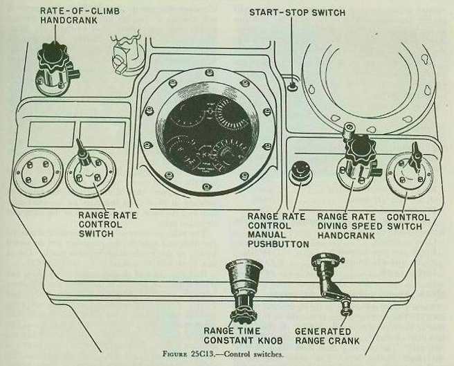
The right front dial of the group shows negative range rate or diving speed. It is used only for dive attacks. In such attacks the target moves virtually along the line of sight, making its total relative motion equal to negative dR. This rate is set on the dial manually by a special knob: the range-rate/diving-speed knob. See figure 25C13. This knob has a two-position lever like the A and Sh knobs. The lever is shifted to HAND (for dive attacks only) for manual operation. It is left at AUTO at all other times, so the rate control mechanism will be free to function as described in article 25C7.
The time dials located at the left rear of the window show time in minutes and seconds. The ring dial indicates minutes, while the inner dial reads seconds. Driven by the computer time motor, these dials are used in conducting maintenance tests. They can be set manually by the time crank. Pushing the crank IN causes the minute ring dial to return to zero automatically. Then the crank, still IN, is turned to set the inner, second dial against a fixed index. With the time motor not functioning, the time crank in the OUT position can be used to turn all shafts transmitting time in the computer. A small dial near the center of the window is designed to rotate twice each second. Checking this dial with a clock or watch, the operator can rotate the time crank by hand to supply the computer with time input if the time motor fails.
25C14. Control switches
There are two switches located at the computer range operator’s station on the front top edge of the control section as shown in figure 25C13. These switches are the control switch and the range rate control switch. They are used to select the method of rate controlling and computer operation.
The control switch has three positions: NORMAL, TEST, and LOCAL. Positioning the switch causes changes in the computer electrical circuits required by the methods of rate control for bearing and elevation and for operation of the computer without director inputs. With the control switch on NORMAL, bearing and elevation rate corrections are introduced into the rate control mechanism by the director trainer and pointer turning their handwheels with the rate control keys closed. This is the method of rate controlling called automatic rate control — discussed in paragraph 25C6 (3)(a) — and is employed against all air targets as well as surface targets at speeds of 15 knots or greater.
With the control switch in the TEST position, manual rate control only is possible. Changes in A, Sh, and dH (for air targets) are made manually by computer operators until the generated bearing and elevation dials are rotating at the same rate as the observed dials. This method of rate control must be used for targets at speeds below 15 knots as explained in paragraph 25C6 (3)(b). The rate control mechanism does not function with the switch at TEST.
With the control switch at LOCAL, director inputs are prevented from entering the computer, and the computer solution is based upon its own generated value of relative target bearing. This allows the computer to be used for indirect fire against a surface target when the target is not visible from the director. Range and target bearing are obtained from a source other than the director, such as combat information center, and entered manually into the computer.
The rate control mechanism does not function with the control switch at LOCAL. The range rate control switch has two positions: AUTO and MANUAL. Positioning the switch causes changes in the computer electrical circuits required by the methods for rate controlling in range and described in article 25C9. With the switch at AUTO, either the rangefinder operator or the radar operator in the director initiates the rate control corrections in the computer. With the switch at MANUAL, rate controlling in range is performed at the computer by the computer (range) operator. The rate control mechanism will function for either position of the range rate control switch unless the rate control mechanism is made inoperative by positioning the control switch at TEST or LOCAL.
While the control switch and the range rate control switch are not tied together, neither will permit the rate control mechanism to function properly unless the four shift levers are all at AUTO. These shift levers are on the A knob, the dH knob, the Sh knob, and the range-rate/diving-speed knob.
Normal operation of the computer employs the automatic rate control mechanism, and is obtained by the following switch positions — Control switch: NORMAL; Range rate control switch: AUTO or MANUAL; A, Sh, dH, and diving-speed knobs: AUTO.
Manual operation of the computer requires that the computer crew employ manual rate control methods, and requires the following switch positions — Control switch: TEST; Range rate control switch: MANUAL; A, Sh, and dH knobs: HAND; Diving speed: AUTO.
Local operation of the computer requires the following switch positions — Control switch: LOCAL; Range rate control switch: MANUAL; A, Sh, and dH knobs: HAND; Diving speed: AUTO.
25C15. Bearing and elevation dial groups


These groups are shown in figures 25C14 and 25C15. The bearing group is located at the right rear of the control unit (fig. 25C2). It consists of two pairs of dials, each having an inner dial and a ring dial. The two ring dials show observed relative target bearing (Br). The coarse ring dial is graduated through 360 degrees, while the fine ring dial is graduated through 10 degrees of Br. The inner dial of the fine dial group has 10 equally spaced scribe marks only. This dial is driven by generated relative target bearing (cBr). When the control switch is at NORMAL or LOCAL, the cBr dial is driven by the bearing follow-up motors, which cause it to rotate automatically at the same rate as the fine Br dial. When the control switch is at TEST, these dials rotate together only when the computer solution is correct. Any difference in the speeds of rotation of these dials indicates an incorrect solution and the need for a correction to the computed bearing rate.
Located at the left rear of the control unit is the elevation dial group (fig. 25C2). This group is very similar to the bearing group except for the graduations and values used to drive the dials. The two ring dials (fig. 25C14) show observed target elevation (E). Within the fine-ring E dial is the inner dial inscribed with 10 equally spaced scribe marks only. This dial is driven by the values of generated target elevation (cE). The inner dial of the coarse-ring E dial is blank and does not rotate. When the control switch is at NORMAL, the cE dial is driven by an elevation follow-up motor which causes it to rotate automatically at the same rate as the fine E dial. When the control switch is at LOCAL, the elevation dials will show 0° target elevation, since the local position is used for surface fire only and there are no director inputs.
With the control switch at TEST, the fine E dial and the cE dial rotate together only when the solution is correct. Any difference in the speeds of rotation of these dials indicates an incorrect solution and the need for a correction to the computed elevation rate.
The value of observed target elevation shown on the dials and used in the computer can be varied by use of the synchronize-elevation knob. Use of this knob will be described in article 25C17.
Both bearing and elevation dial groups have two small indicators located at the edges about halfway between the ring dials. See figures 25C14 and 25C15. One of these indicators shows red when the rate control key in the director is closed. The other indicator is a dial having two black and two white quadrants. This indicator rotates when the director trainer (pointer) turns his handwheels in automatic rate control. It is called a solution indicator. A red signal and a moving solution indicator show that rate corrections are entering the computer’s rate control mechanism. As explained earlier, this statement is true only if the four shift levers are thrown to AUTO.
25C16. Range and height dial group
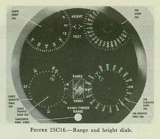
This dial group is shown in figure 25C16. It is located at the front center of the control unit (see fig. 25C2). It consists of two sets of dials — one for range and one for height. The two dials at the rear of this group show coarse and fine values of generated target height (cH). This quantity is not used in normal operation of the computer.
The range dials consist of two pairs of ring and inner dials. From left to right, the ring dials indicate coarse and fine values of generated present range (cR). Within each ring dial is a dial inscribed with a pointer only. From left to right, these dials are driven by coarse and fine values of observed present range (R). For proper operation of the computer, observed and generated present ranges must be equal, because the instrument uses cR for its calculations. When the range rate control switch is at AUTO, the range follow-up motor drives the cR dial to keep it matched with and rotating at the same rate as the R dial. When the dials are matched, the zero marks on the ring dials (cR) are opposite the pointers on the inner dials (R) as shown in figure 25C16. When so matched, the value of cR equals the value of R and can be read at the fixed indexes.
When the range rate control switch is at MANUAL, the range follow-up motor is de-energized, and the computer range operator, using the generated range handcrank, must match the cR dials with the R dials, thereby introducing the correct value of cR into the computer. If the computed value of range rate (dR) is correct, the R and cR dials will stay matched and rotate at the same speeds. If the computed value of range rate (dR) is not correct, the cR and R dials will not rotate at the same speeds, and consequently the dials will not remain matched. The computer range operator, then, must rematch the range dials and at the same time introduce range rate corrections into the rate control mechanisms. This is accomplished by turning the generated range handcrank and depressing the computer range rate control manual push button as explained in article 25C9.
The generated range crank has two positions — OUT and IN. At the OUT position, the crank introduces and corrects cR by turning the cR dials, but does not affect range rate. When the crank is IN, it accomplishes the same thing plus introducing range rate corrections if the range rate control manual push button is depressed.
The computer is limited mechanically to a maximum tracking range of 35,000 yards. Accordingly, the coarse cR ring dial is graduated only to 35,000 yards. When the computer range limit is reached, the cR ring dial stops, but the pointer on the inner R dial continues to turn. This indicates to the operator that the actual range is beyond the computer limit, and it gives some idea of what the target is doing.
25C17. Synchronize-elevation and dip dials
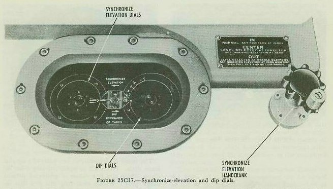
This dial group and the associated knob are shown in figure 25C17. They are located on the indicator section just below the star-shell computer (see fig. 25C2). The function of the synchronize-elevation mechanism is to interrupt the computer elevation shafting in order to permit the Computer Mark 1A to be used for methods of fire which can be employed against surface targets, but which usually are not practical against air targets. The ensuing discussion will explain the use of the synchronize-elevation mechanism in each of its three positions: IN, CENTER, and OUT.
1. IN position. With the synchronize-elevation knob in the IN position, the value of E used in the computing section of the computer is adjusted to the value of E obtained by combining L with Eb being measured by the director. This is done by matching the synchronize-elevation dials against the index (see fig. 25C17), which allows elevation (Eb − L) to drive through the differential (D-12) unchanged (see fig. 25C18). The synchronize-elevation knob is always placed in the IN position and the synchronize-elevation dial matched, except for special types of surface fire.

Figure 25C18 shows the operation of the synchronize-elevation knob in the IN position. The knob is turned against brake pressure until the synchronize-elevation dials are matched. This introduces zero difference between right and left E shafts of differential D-12, and the friction brake prevents further turning of the shaft or synchronize-elevation dial. The output of differential D-11 then passes through differential D-12 unchanged, and is used in the generating and prediction mechanism to compute Vs as shown in figure 25C18.
2. CENTER position. In certain special types of surface fire the quantity Eb minus L is not introduced into the computing mechanism. For example, using selected elevation aiming, the director sights do not continuously remain on the target, but are fixed in relation to the deck. When the line of sight is off target in elevation, the combination of fixed Eb and changing L produces inaccurate values of E which must not be allowed to enter the generating and prediction mechanism.
Placing the synchronize-elevation knob in the CENTER position accomplishes two things. First, the inaccurate value of E is kept out of the generating and prediction mechanism by interrupting its transmission through the elevation shafting to the generating and prediction mechanism at differential D-12. Secondly, the elevation shafting leading out of differential D-12 and into the computing section is positioned by turning the synchronize-elevation knob. The shaft is always positioned at zero elevation, because the actual surface target elevation is close to that value. This value of E is used in the computer only for the computation of Vs.

Figure 25C19 illustrates the elevation lines when a selected Eb is used. Note that the meaningless value of E is prevented from entering the computing section by the friction brake on the E shafting to the right of differential D-12. Instead, the inaccurate value of E drives out the other side of differential D-12 and merely rotates the synchronize-elevation dials, which have no meaning in this case.
The synchronize-elevation knob is geared to the E shaft of the computing mechanism, and is turned against brake pressure until the computer elevation dials (fig. 25C14) read zero. The selected value of Eb is combined in differential D-17 with Vs and Vz to give a fixed gun elevation order which is correct only at the instant the pointer’s crosshair is on the target.
3. OUT position. The synchronize-elevation knob is placed in the OUT position when no value of Eb is received from the director. This is always the case during indirect fire, such as the bombardment of a hidden target. It is possible to fire without the aid of the Eb input by correctly positioning the Eb shafting at the computer with a substitute value of Eb.
The elevation shafting into the generating and prediction mechanism and to the elevation dials is placed at the zero value of elevation by turning the synchronize-elevation knob in the CENTER position as described above. The knob is then placed in the OUT position, which cuts out the input of Eb from the director. The value of dip angle is then set on the Eb shafting by matching the dip dial reading to R2, which the operator reads on the R2 counter. See figure 25C17.


Since the computation of gun elevation order is based on the angle Eb, a substitute value of Eb must be provided when the director is not used. This substitute value of Eb must closely approximate the value ordinarily supplied by the director. The substitute value of Eb is composed of L from the stable element, plus dip.
As shown in figure 25C21, dip to the target is the angle between the horizontal and a line of sight to the waterline of a surface target. This should not be confused with dip to the horizon. Dip is a function of range.
The graduations on the dip dial are spaced so that, when the index on the inner dial is under the fixed index and the value of range is at the fixed index, the dip-dial shafting is positioned at the corresponding value of dip. The dial is usually set to R2, because of the convenient location of the R2 counter to the dip dial and knob.
Figure 25C20 illustrates the elevation lines when the director is not furnishing Eb. First the E shafting into the generating and prediction mechanism is set to zero by turning the synchronize-elevation knob in the CENTER position as previously described. Then, with the knob in the OUT position, the dip dial is set according to the value of R2. This positions the shafting between the differentials D-11 and D-12 at the value of dip angle. Note that this setting does not drive into the generating and prediction mechanism, because the brake to the right of differential D-12 is set. L is combined with dip in differential D-11 to position the Eb shafting correctly as a substitute value of Eb which very closely approximates the corresponding observed value.
Finally, when it is desired to return to normal, continuous-aim fire, the synchronize-elevation knob is returned to the IN position. This releases the brake to the right of differential D-12. In this position it is turned to align the synchronize-elevation dials with their fixed index, and in so doing realigns the E shafts on both sides of differential D-12 to make E the same on both sides. This again allows the correct value of Eb, as measured by the director, minus level (L), to drive through differential D-12 to the generating and prediction mechanism unchanged.
25C18. Spot indicators

Figure 25C22 shows the three spot indicators and their associated knobs. The entire group is located at the right of the indicator unit, as shown in figure 25C1, when viewed by a man facing the indicator unit. Elevation and deflection spots are shown on dials against fixed indexes from minus 180 mils to plus 180 mils. Range spots are shown on two counters. One counter indicates ADD spots to a maximum of 1,800 yards. The other counter reads DROP spots to a limit of 12,000 yards. The large DROP limit is provided for control of main-battery guns. Spots are received from the director and are normally applied electrically in the computer. However, spot knobs are available for manual settings. For electrical (automatic) reception, the knobs must be locked OUT, while they must be locked IN for manual operation.
The three spot receivers can get out of synchronization with their incoming signals. To prevent this, check to see that the dials and counters indicate proper values before shifting from manual to automatic operation.
25C19. Sight deflection, sight angle, fuze-setting order, and advance range indicators
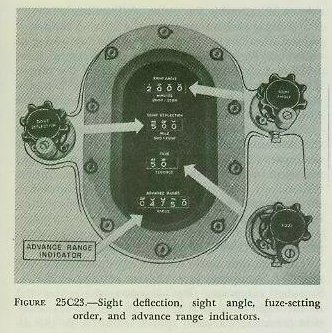
This group of indicators and their associated dials are shown in figure 25C23. The group is located at the left rear of the indicator unit, next to the spot indicators, as shown in figure 25C1. This group includes four sets of counters that show the computed values of sight angle, sight deflection, fuze-setting order, and advance range. Sight angle is shown in minutes of arc, with 2,000 as the zero value. Sight deflection in mils has 500 as the zero value. Fuze-setting order is indicated in seconds of time, while advance range is shown in yards. All but advance range (R2) are normally sent to the guns electrically as computed by the instrument. However, there are three knobs for manual setting of the sight angle, sight deflection, and fuze orders. Manual operation is used with arbitrary values in connection with the control of main-battery guns, and in shore bombardment. Advance range is transmitted only to the star-shell computer. The indicated value of R2 is used with the dip dials, as described in article 25C17, and for checking purposes.
25C20. Other knobs, dials, and switches
Figure 25C1 shows the location and appearance of some of the knobs, dials, and switches mentioned in this article:
1. Initial velocity dial(s) and knob(s). Depending upon the modification of Computer Mark 1A, one or two I.V. knobs and dials are installed to permit setting manually the existing average initial velocity of the battery. The dials are graduated in feet per second between correct I.V. limits for the guns controlled by the computer. For the computer designed to control 5"/38 gun mounts, I.V. settings can be made between 2,350 fs and 2,600 fs. When two dials and knobs are installed, the same setting accounts for I.V. loss due to erosion, variations due to powder temperature, and compensation for air-density variations.
2. Dead-time dial and knob. The dead-time dial shows dead time (Tg), the time in seconds between setting of the fuze and firing of the projectile. The dial is graduated from 0 to 6 seconds, but varies with the average loading interval of the gun crews.
3. Power switch. The power switch energizes all the servo receivers which drive the various quantities into the computer mechanisms.
4. Time push button and director trainer’s rate control key. With the power switch ON, the computer time motor circuit is energized up to a switch called the time motor switch. This latter switch is located inside the computer and is controlled by the time push button and the director trainer’s rate control key as explained below. The time push button is located on top of the computer, to the left of the time dials. With the power switch ON and the control switch at NORMAL, either closing the director trainer’s rate control key or depressing the time push button starts the time motor. Once the time motor has been started, however, it can be stopped only by depressing the time push button. Thus, in normal operation employing automatic rate control, the computer will start tracking when the director trainer is on target and closes his rate control key. At the end of the tracking run, the computer range operator depresses the time push button to stop the time motor. With the power switch ON and the control switch at either TEST or LOCAL, the time motor can be started and stopped only by alternately depressing the time push button. Thus, when employing manual rate control or local computer operation, the computer range operator must start and stop computer tracking.
5. Air-surface selector switch, sensitivity push button, range time constant knob. Figure 25C1 shows these controls, which were discussed in articles 25C9 and 25C10.
6. Other dials. On the sides of the corrector section are a number of dials used for test purposes. These dials show the following values: gun train order (B′gr); gun elevation order (E′g); unit train parallax (Ph); unit elevation parallax (Pv), for aircraft carriers only; level (L); crosslevel (Zd); elevation trunnion-tilt correction (Vz); and deck deflection (Dd).
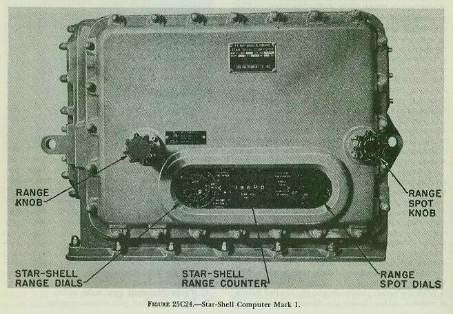
25C21. Star-shell computer
The Star-Shell Computer Mark 1 Mod 0 is designed to control dual-purpose guns for star-shell fire. The star-shell computer will control the illumination of a target which has been detected and for which gun orders are being computed by the Computer Mark 1A. Whereas the Computer Mark 1A computes gun orders to hit a given target, the star-shell computer utilizes those gun orders to calculate another set of gun orders to illuminate that same target. The instrument is mounted integrally with the main computer on the indicator section as shown in figure 25C2. Its appearance is shown in figure 25C24.
25C22. Star-shell computer, functions
The star-shell computer’s functions are to compute and transmit the following for control of the guns firing star shells:
1. B′grjn — Star-shell gun train order.
2. E′gjn — Star-shell gun elevation order.
3. Fn — Star-shell fuze-setting order.
By positioning the proper switches at the fire control switchboard, these outputs are transmitted to the guns firing star shells over the regular circuits used for gun train, gun elevation, and fuze-setting orders from Computer Mark 1A. They are derived from the following inputs:
Mechanical from the computer: B′gr (gun train order); E′g (gun elevation order); R2 (advance range); WrD + KRdBs (star-shell deflection rate).
Electrical from the star-shell spot transmitter in the director: B′jn (star-shell deflection spot); E′jn (star-shell elevation spot); Rjn (star-shell range spot).
Manual: Rjn (star-shell range spot); R2n (star-shell range).
Star-shell deflection rate (WrD + KRdBs) is used to correct B′gr (from Computer Mark 1A) for motion of the star due to wind and relative target motion such that, at half the burning life of the star (about 30 seconds), the point of illumination is in the vertical plane containing the line of sight and behind the target. Star-shell fuze (Fn) and gun elevation (E′gjn) orders will cause the star to form 1,500 feet above and 1,000 yards beyond the target. Thus E′gjn must include a correction to compensate for the fall of the star between the time the projectile bursts and the star is formed.
Star-shell range spots (Rjn) are used to alter both the elevation and the fuze orders. Star-shell deflection spots (B′jn) and star-shell elevation spots (E′jn) are used to correct the train and elevation orders respectively. All spots normally are transmitted to the star-shell computer by the star-shell spot transmitter in the director.
25C23. Star-shell computer, operation
The dials and knobs used in the operation of the star-shell computer are shown in figure 25C24. Star-shell range spot (Rjn) is sent to the center dial in the right-hand dial group by synchro transmission from the star-shell spot transmitter in the director. The only marking on the center dial is the white pointer shown in the figure. The ring dial is graduated to read spots applied to the instrument against the fixed index shown in the figure, and is rotated by the range spot knob. To introduce Rjn into the computing mechanism of the instrument, the operator turns the range spot knob to place the index on the ring dial opposite the pointer on the center dial.
Star-shell range (R2n), which is the horizontal advance range measured to the point of the star-shell burst, is displayed on the counter between the two dial groups to enable the operator to read the correct value of R2n required as the input to the left-hand dial group.
The dial group to the left of the instrument (labeled star-shell range dials) consists of an inner dial and a ring dial, both of which indicate star-shell range (R2n) against the fixed index. The inner dial is the fuze dial, and is graduated to compute Fn as a function of R2n. By pushing the range knob to its IN position and setting the value of R2n against the fixed index, star-shell fuze order is set into the instrument. The ring dial supplies inputs to the instrument required in the computation of star-shell gun train and elevation orders. To enter the correct input into the instrument, the range knob is pulled to its OUT position and turned to make the ring dial read the correct value of R2n against the fixed index.
In order to operate the star-shell computer, Computer Mark 1A must be set up for control of surface fire against the target to be illuminated by the star-shell fire. The main computer can be used to control the guns firing service projectiles against the same target. However, if spots are introduced for the service projectiles, they must be neutralized by opposite spots at the star-shell spot transmitter, since the star-shell gun orders are based upon the Computer Mark 1A gun orders.
25C24. Personnel
The full operating crew for the computer consists of a range operator, a bearing operator, an elevation operator, a synchronize-elevation operator, and a star-shell computer operator. In addition, a stable element operator and a switchboard operator are required for each computer-stable element combination. The synchronize-elevation operator and the star-shell computer operator usually double as the sight setter’s talker and fuze setter’s talker to the guns, since they can readily read the dials on the computer indicator section. When manual follow-up of the stable element is required, usually one of the latter two operators assists in this operation.
The computer crew on ships with one computer-stable element combination to a plotting room is under the immediate direction of the plotting-room officer, who does not usually function as an operator. In plotting rooms containing two systems, each computer crew usually is supervised by a junior officer in charge of one computer-stable element combination.
D. Mark 6 Stable Element
25D1. Introduction
The Mark 6 stable element (fig. 25D5) is one of the three major units of the Mark 37 gun fire control system. It is located in the plotting room adjacent to the Mark 1A computer, as shown in figure 25C2. In general, the primary function of the Mark 6 stable element is equivalent to that of the stable vertical in the main-battery system; that is, it measures level angle (L) and crosslevel angle (Zd) — angles caused by the variation of the position of the deck of the ship with respect to the horizontal and hence required in the solution of the fire control problem. As will be explained in subsequent articles, the stable element accomplishes this function by using a gyroscope to establish the true vertical and its associated true horizontal plane.
25D2. Gyroscopic principles
As explained in article 19G2, a gyroscope has two properties that make it useful in fire control. These properties are gyroscopic inertia, and precession. Because of its inertia, a spinning gyro tends to keep its axis pointed in a fixed direction in space. Because of precession, it tends to tilt its axis in a direction at right angles to that of any force applied to it.
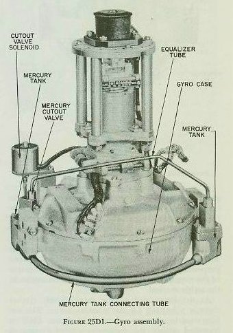
25D3. Righting system
Solution of the fire control problem requires that we know the true vertical and horizontal, so that the level angle (L) and crosslevel angle (Zd) can be measured. In the Mark 6 stable element, the righting system makes the gyro axis assume and maintain a true vertical position. This system has two principal parts: the mercury control system and the latitude correction system.
Mercury control system. This system introduces a righting force which causes the gyro spin axis to precess to the vertical and, in addition, counteracts the effects of friction, acceleration forces, shocks, and other disturbances which would tend to displace the spin axis from the vertical.
Essentially the mercury control system consists of two tanks containing mercury, attached to the casing which houses the gyro wheel, on diametrically opposite sides of the wheel. These two tanks are joined by two narrow connecting tubes as shown in figure 19G4. The top tube is merely an air-pressure equalizing connection between the two tanks. The lower tube permits the free flow of mercury from either tank to the other. As long as the gyro wheel is exactly horizontal, the mercury level in both tanks will be the same; but as soon as the wheel is tilted from the horizontal by some external force, gravity will cause mercury to flow from the high tank to the low tank. The additional mercury in the low tank will then produce the same effect as a downward pressure exerted at the low point of the gyro wheel.
Application of the rule of precession shows that this will only cause the wheel to precess more out of the horizontal in a direction 90° away. However, if the mercury effect is applied not at the low point but 90° from the low point, pressure at this point will cause the low point of the gyro to precess upward to its original horizontal position, at which point the mercury is redistributed equally.
This effect is accomplished in the stable element (1) by a gimbal rotation motor which rotates the entire gyro assembly and attached mercury tanks at 18 rpm in the same direction as gyro spin, and (2) by installation of an orifice to regulate the flow of mercury in the lower connecting tube. The net result is that, by the time the mercury has reached the low tank, the low tank has been displaced 90° from the low point of the gyro wheel, and the pressure exerted here causes the gyro spin axis to precess back into the vertical. This, moreover, is exactly what takes place when the gyro is first started. As a result of mercury flow and gimbal rotation, the gyro spin axis automatically erects itself and settles in the vertical after several minutes of operation.
At times certain irregularities of ship motion, such as sharp turns or speed changes, occur which cause an irregular flow of mercury, tending (as the result of either centrifugal force or inertia) to displace the gyro spin axis from the vertical rather than to right it. To prevent mercury flow at such times, a mercury cut-out valve closes, thus blocking the lower connecting tube. This valve is operated automatically by a cut-out control on the stable element’s control panel.
Latitude correction system. It was shown above that the mercury control system brings the spin axis of the gyro to the vertical. However, effective operation of that system depends upon a definite displacement of the spin axis from the vertical. Consequently, if the mercury control system were to act alone, the gyro spin axis still would deviate slightly from the vertical as a result of the apparent tilt caused by the earth’s rotation. In other words, the spin axis would be continuously lagging, but attempting to regain, its vertical position.
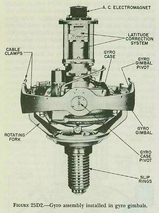
Figure 19G3 depicts the effect of the earth’s rotation on a free gyro. A gyro located at either pole, such as gyro A in the center illustration, will be unaffected by the earth’s rotation, inasmuch as a plane tangent to the earth at either of these points remains parallel to its original position in space.
On the other hand, a gyro located at the equator will assume the successive positions with respect to the earth shown in the left-hand illustration. To an observer standing on the earth, the wheel will appear to turn completely over every 12 hours; that is, to turn backward (toward the west) with respect to the earth’s rotation at the rate of one revolution every 24 hours.
At any point between the pole and the equator, as shown in the center and right-hand illustrations, the gyro wheel will appear to gyrate once every 24 hours about an axis parallel to the axis of the earth’s rotation and in a direction opposite to that of the earth’s rotation. This effect can be compensated for if the gyro can be made to precess slowly to the eastward at the same rate as the earth’s rotation. The gyro’s plane of rotation will then remain parallel to the horizontal plane.
This is accomplished in the stable element by means of a latitude correction system which consists essentially of a latitude weight and a latitude motor. The latitude weight is so arranged as to cause a downward pressure at the north point of the gyro wheel, resulting in an easterly precession. The position of the latitude weight is adjustable, so that the weight can be set for the latitude in which the ship is operating. Usually it is considered sufficient to make a latitude setting once a day.
To ensure that the latitude weight remains properly oriented in a northerly direction so as to cause easterly precession of the gyro, certain factors must be taken into consideration. The latitude weight, as shown in figure 25D2, is mounted at the upper end of the gyro assembly. The gyro assembly, however, does not remain stationary. It turns with the ship (in a horizontal sense) during a change of course (Co); it is rotated by director train (B′r), as will be explained in a subsequent article, to permit proper measurement of level angle (L) and crosslevel angle (Zd); and, finally, it revolves at 18 rpm to permit proper operation of the mercury control system as previously pointed out. Obviously then, provision must be made to cancel out the effects of Co, B′r, and 18 rpm if the latitude weight is to remain in a northerly direction.
This is done in the stable element by a synchro known as the latitude motor. The rotor of this motor supports the latitude weight, and the stator is attached to the gyro case. The electrical input to the motor positions the rotor with respect to the stator. Consequently this input must be the sum of own-ship course (Co), training gear rotation (B′r), and gimbal rotation (18 rpm) if the latitude weight is to remain properly oriented.
Two differential generators, which, in effect, are electrical differentials, are employed to make up this electrical input to the latitude motor. As illustrated schematically in figure 25D6, input Co goes to the director train differential (mounted in the base of the instrument) where B′r is added to it. The sum, Co + B′r, goes to the gimbal rotation differential (mounted on the level frame). There 18 rpm is continuously added to Co + B′r. The output to the latitude motor stator, Co + B′r + 18 rpm, holds the latitude motor’s rotor stationary with the weight in a northerly direction — the 18 rpm effectively stopping the rotor on the LOS, B′r effectively bringing the rotor to the fore-and-aft axis of the ship, and Co orienting the rotor to North.
25D4. Mechanical construction
The Mark 6 stable element, like the stable vertical used in the main-battery fire control system, consists essentially of a sensitive element and a measuring group.
Sensitive element. This is the heart of the instrument and consists of the gyro, gyro case, gyro gimbal, and a fork-shaped support known as the rotating fork. Figures 25D1 and 25D2 illustrate these parts in the stable vertical’s sensitive element. Corresponding parts in the stable element are essentially the same.
Figure 25D1 shows the gyro proper. The wheel is carried on an axle supported by ball bearings at the upper and lower ends of the gyro case, the wheel and case forming the rotor and stator respectively of a high-frequency induction motor. A squirrel-cage winding, consisting of solid conducting bars, is in the gyro wheel, while wire stator windings are in the gyro case. A special motor-generator is provided to supply power at a frequency sufficient to drive the gyro at about 8,500 revolutions per minute.
The gyro assembly of figure 25D1 pivots within the gyro gimbal on a case axis perpendicular to the spin axis, as shown in figure 25D2. The gyro gimbal, in turn, is supported by the arm of the rotating fork on the gimbal axis, which is perpendicular to both the case axis and the spin axis. This axis arrangement provides a universal mounting giving the gyro three degrees of freedom, and allows it to spin on a vertical axis, even though the rotating fork may vary its position from time to time.
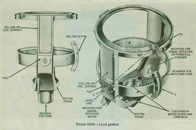
Measuring group. This consists of a level gimbal, a crosslevel gimbal, training gear, and, as will be described more in detail in a subsequent article, an umbrella and its follow-up coils. Figures 25D3 and 25D4 illustrate the stable vertical’s measuring group. The measuring group of the stable element is not entirely the same. The important difference lies in the manner in which level angle (L) and crosslevel angle (Zd) are measured. In the stable element, the outer gimbal is the crosslevel gimbal, supported at its trunnion bearings by the training gear structure (main frame). The outer (crosslevel) gimbal, in turn, supports the inner or level gimbal so that the gimbal axes are mutually perpendicular. It can be seen from this gimbal relationship that, in the stable element, L is measured in a vertical plane while Zd is measured in a plane perpendicular to the deck. This is just the reverse of the measurement of level and crosslevel angles in the stable vertical.
At the lower end of the inner (level) gimbal there is a bearing for the rotating fork. The entire sensitive-element assembly of figure 25D2 is mounted within the measuring-gimbal system of figure 25D3, being supported at its lower end by the rotating fork in this fork bearing, so that it is free to rotate within the measuring group. The complete assembly is shown in figure 25D4. A gimbal rotation motor, attached to the lower end of the inner (level) gimbal, is geared to the rotating fork and drives it at 18 rpm. The fork turns the entire sensitive element at this speed within the measuring-gimbal system. This rotation is essential to the mercury control system as explained in article 25D3.
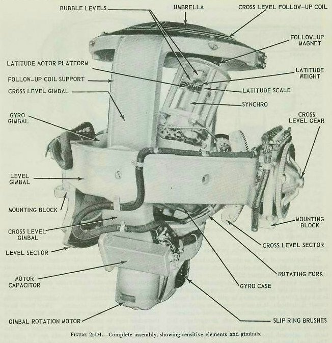
25D5. Follow-up system
The actual measurement of level angle (L) and crosslevel angle (Zd) in the stable element is similar to the measurement of comparable angles in the stable vertical, and is accomplished by a follow-up system. This system centers about an electromagnet, called a follow-up magnet, and two follow-up coils.
The umbrella is attached to and moves with the top of the level gimbal. It contains two follow-up coils. The level follow-up coil is imbedded in grooves on the upper side of the umbrella, while the crosslevel follow-up coil is similarly carried on the underside. In effect, each coil is wound in the shape of a figure eight, the turns being clockwise in one loop and counterclockwise in the other.
The line joining the loop centers of the level coil is at right angles to the level axis, which means that it lies in the vertical plane through the LOS when the training gear is oriented by B′r. The corresponding line of the crosslevel coil is at a right angle to the crosslevel axis, and therefore lies across the vertical plane through the LOS. The center of each figure-eight coil is on the umbrella center.
The follow-up magnet is mounted on top of the gyro case, as shown in figure 25D2, so that its axis coincides with the spin axis. The magnet is energized with alternating current which sets up an alternating magnetic field. This field induces voltages in the follow-up coils. The action of the crosslevel follow-up is the same as that of the level follow-up; hence the rest of this discussion is confined to the level system.
When the umbrella center is on the spin axis, the voltages induced in the two loops of the level coil are equal in magnitude. Since the loops are wound in opposite directions, their voltages at any instant, however, have opposite polarity, and their resultant voltage is zero. When a change in level angle occurs (during rolling or pitching of the ship), the umbrella, which tends to follow the ship, moves off the spin axis in the vertical plane through the LOS. The follow-up magnet, however, remains in the vertical because of the action of the gyro. Consequently, the magnet is then closer to one loop of the level follow-up coil than to the other, and induces a higher voltage in the first loop than in the second.
The resultant voltage across the coil is no longer zero, but has both magnitude and direction which provide an indication of the follow-up action required. The amount that a follow-up must drive automatically — or that a handcrank must be turned manually — to reposition the level gimbal in the horizontal plane, and hence to return the umbrella to its neutral position on the spin axis, is a measure of level angle (L).
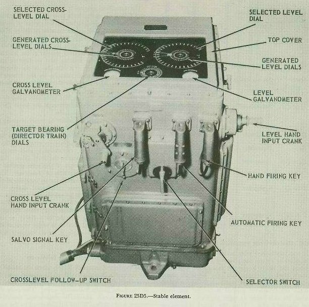
25D6. Keys, dials, handcranks, switches
The locations of most of the various keys, dials, handcranks and switches of the Mark 6 stable element can be seen in figure 25D5.
Keys. There are three hand-operated keys on the front of the instrument. The right-hand key is a hand firing key that may be put into the firing circuit if desired. It is in no way connected with the internal arrangement of the stable element. The middle key is the automatic firing key. It operates in conjunction with automatic firing contacts in selected level or selected crosslevel fire. The third key is the salvo-signal key. It is used to sound buzzers in the mounts as a warning just before the firing circuit is closed.
Dials. There are three sets of dials under the square window at the top of the instrument. The pair of concentric dials at the front and center indicate the fine and coarse values of director train B′r against a fixed index. The two remaining sets of dials each consist of a trio of concentric dials. The inner and intermediate dials respectively indicate fine and coarse generated values against a fixed index. The outer ring dial indicates the selected value against the same index when selected values are being used. The right-hand set of dials registers values of level, while the left-hand set indicates crosslevel. Two galvanometers are located on the top of the instrument, one for level and one for crosslevel. These galvanometers are used in conjunction with the handcranks described below during manual follow-up.
Handcranks. There are two hand-input cranks installed on the stable element. They both have two separate and distinct uses. First, either one or the other may be used to put in a selected value, but both cannot be used simultaneously for this purpose. Secondly, the handcranks can be used in manual follow-up, a procedure which was mentioned in article 25D5 and which will be explained in detail in a subsequent article.
Neither handcrank can simultaneously accomplish both uses. If, for example, the level handcrank were constantly being rotated for manual follow-up in level (to keep the level follow-up coils centered over the follow-up magnet), it could not concurrently be used to set in a selected value of level. Both handcranks are either engaged or disengaged by magnetic clutches which are controlled by the selector and follow-up switches described below.
Switches. Three switches are installed on the stable element for its control. They are: the selector switch, the crosslevel follow-up switch, and the level follow-up switch. The first two can be seen on the front of the instrument in figure 25D5. The third is located to the right of the level hand-input crank on the right side of the instrument.
The selector switch is used in selecting the type of fire desired. It has three positions labeled LEVEL FIRE, CONTINUOUS FIRE, and CROSSLEVEL FIRE. When the selector switch is thrown to a selected type of fire (for instance, level or crosslevel), it causes the corresponding handcrank to become engaged.
The two follow-up switches, which are identical in operation, control the method of follow-up used. Each has two labeled positions, AUTOMATIC and MANUAL. The switches have nothing to do with the type of fire used but, if a switch is on MANUAL, its corresponding handcrank, already being used for manual follow-up, cannot be used for selected fire. For example, if the level follow-up switch were on MANUAL, selected-level fire could not be used but crosslevel fire could be used; therefore, in this particular instance, the selector switch would have to be on either CONTINUOUS FIRE or CROSSLEVEL FIRE.
25D7. Inputs and outputs
The inputs and outputs of the Mark 6 stable element are summarized below, together with their more important uses. Most of them have been discussed previously, either in the preceding articles or in the study of the Mark 1A computer and the Mark 37 director. It should be noted that all outputs to and inputs from the computer are transmitted mechanically by shafting. On the other hand, Co and the value of Zd sent to the director are both electrically transmitted.
Inputs:
1. B′r — Received from computer. Used to assist in making up L and Zd; to orient gimbals to LOS; to orient latitude weight to North.
2. Co — Received from gyro compass. Used to orient latitude weight to North.
3. Own ship’s latitude — Set manually. Used to counteract the earth’s rotation effect on the gyro.
4. Lj or Zdj — Set manually. Used in selected fire.
Outputs:
1. Zd — To director. To stabilize optics and radar antennas.
2. Zd or Zdj — To computer. To compute Br from B′r; to compute trunnion-tilt correction.
3. L or Lj — To computer. To compute E from Eb, Br from B′r, and trunnion-tilt correction.
4. L + Zd/30 — To computer. To make up elevation correction.
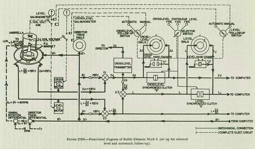
25D8. Director-train transmission
It was mentioned previously that director train (B′r) actually rotates the training gear in the stable element and hence keeps the axis of the crosslevel (outer) gimbal oriented in the vertical plane through the LOS. This is shown in figure 25D6. Within the crosslevel gimbal is carried the level gimbal, its axis being at right angles to the crosslevel gimbal’s axis. Thus the input of director train (B′r) positions both gimbals so that level angle (L) is measured in the vertical plane through the LOS and crosslevel angle (Zd) in a plane at right angles to both the vertical plane through the LOS and the deck plane. The quantity B′r, in addition, has other uses. It drives the director train dials on top of the stable element; it assists in holding the latitude weight in a northerly direction as explained in article 25D3; and finally, it is used in determining crosslevel angle (Zd) and level angle plus crosslevel function (L + Zd/30) as will be explained in a subsequent article.
25D9. Gear walking
The crosslevel gimbal is connected to the crosslevel follow-up motor by a gear train and shafting which may be driven either by the motor or by the crosslevel handcrank as can be seen in figure 25D6. The drive passes through the training gear. When the latter turns, a pinion in the gear train “walks” on another gear in a manner similar to the walking of the pinion on the floating gear in director telescopes. This walking is a function of the director train, f(B′r), similar in nature to the crosslevel function Zd/30. The follow-up motor (or handcrank) must therefore supply the quantity Zd + f(B′r) to the shaft driving the crosslevel gimbal, in order to move the gimbal through the angle Zd to its original horizontal position.
The level gearing is similar in many respects to the crosslevel gearing. However, in addition to passing through the training gear it also has to pass through the crosslevel gimbal to reach the level gimbal. Consequently, crosslevel gimbal motion causes walking of a pinion in the level drive. This gear walking causes motion of the level gimbal in an amount equal to a function of crosslevel. This motion must be compensated for by rotation of the level shafting. The gear ratio used makes this function equal to Zd/30 to match the function required at the director telescopes. The level follow-up motor (or the level handcrank) must therefore supply the quantity L + Zd/30 + f(B′r) to the shaft driving the level gimbal in order to move the gimbal through the angle L to its original horizontal position.
25D10. Operation: automatic follow-up
As explained in article 25D5, when the center of the umbrella moves away from its neutral position over the follow-up magnet, a voltage is induced in at least one of the follow-up coils. The only difference between automatic follow-up, described herein, and manual follow-up presented in the next article, is the manner in which this follow-up coil voltage is employed. For example, when the level follow-up switch is set on AUTOMATIC, it connects the level coil to the level follow-up units on the control and follow-up panel.
At the panel, the coil voltage is amplified and used to control rectifier tubes which supply direct current to the level follow-up motor. The direction of the current flow determines the direction of motor rotation. The current is applied so that the motor drives the level ring in a direction that will place the umbrella center back on the spin axis. The amount that the level follow-up motor will drive, of course, as explained in article 25D9 and as shown in figure 25D6, is the quantity L + Zd/30 + f(B′r).
The response is made sufficiently sensitive to cause the umbrella center to remain very nearly in line with the magnet. In other words, the follow-up motor functions practically as soon as displacement begins, so that the generation or measurement of L is continuous. If the motor were permitted to drive until the signal voltage became zero, of course, it would coast, as a result of its inertia, and actually drive the level gimbal and the umbrella slightly beyond their neutral positions (in the horizontal plane and on the spin axis, respectively).
Then the follow-up control would operate to run the motor in the reverse direction, and it again would coast beyond the desired position. To prevent this action, which is called “hunting,” an anti-hunt unit is included in the controls at the panel. It operates to shut off the power slightly before the neutral position is reached. A sensitivity control permits adjustment of this action to suit the requirements of individual ships.
Automatic follow-up in crosslevel is accomplished in the same way as in level; that is, the crosslevel follow-up switch is placed on AUTOMATIC, and the crosslevel follow-up motor drives an amount equal to Zd + f(B′r) to return the umbrella to its neutral position.
25D11. Operation: manual follow-up
Automatic follow-up normally is used in the operation of the stable element. However, in case of failure, one or both of the automatic follow-up systems can be replaced by manual follow-up. For example, if the level follow-up motor is inoperative, manual follow-up in level can be used to keep the umbrella centered on the spin axis and thus to ensure the proper measurement of level angle (L). To accomplish manual follow-up in level, the level follow-up switch is set on MANUAL. This setting does three things: it connects the level follow-up coil directly to the level galvanometer; it breaks the armature field circuit of the level follow-up motor, thus causing the motor to idle; and it causes the level handcrank clutch, labeled D in figure 25D6, to become engaged.
Any voltage applied to the galvanometer displaces its needle from the zero position, the amount of the displacement being a measure of level and the direction indicating the required direction of handcrank rotation. When the needle is displaced, the level handcrank must be turned until the needle once again is at zero. This rotation of the handcrank, in effect, performs the same function as that of the level follow-up motor during automatic follow-up; that is, by driving back through the level-synchronized clutch A and differentials D-2 and D-3 of figure 25D6, it supplies the quantity L + Zd/30 + f(B′r) to the shaft driving the level gimbal and hence returns the umbrella to its neutral or zero-voltage position.
Manual follow-up in crosslevel is accomplished in a similar way. The crosslevel follow-up switch is set on MANUAL; the crosslevel handcrank clutch C is engaged; and the handcrank rotation drives back through the crosslevel-synchronized clutch B and differential D-1 to supply the quantity Zd + f(B′r) to the shaft driving the crosslevel gimbal.
25D12. Operation: continuous-aim fire
The Mark 37 system was designed for continuous-aim fire, and it is so used most of the time, usually with automatic follow-up at the stable element in both level and crosslevel. Manual follow-up can be used, as explained in article 25D10, but ordinarily is considered a standby measure.
In continuous-aim fire, the selector switch is set at the CONTINUOUS FIRE position, and the two follow-up switches at either AUTOMATIC or MANUAL. Values of L, Zd, and L + Zd/30 are transmitted to the computer, and Zd to the director. Before seeing how these values are transmitted, however, it is essential that the control of the four clutches shown in figure 25D6 be understood. There are two different types of clutches: two synchronized clutches, labeled A and B, and two handcrank clutches, which are magnetic clutches, labeled C and D.
Selector switch control of clutches. The selector switch controls all four of the clutches shown in figure 25D6 — the handcrank clutches electrically and the synchronized clutches mechanically. It is relatively simple to remember when these clutches are either engaged or disengaged if certain stable-element operating conditions are considered as “normal.” As pointed out in the first part of this article, continuous-aim fire and automatic follow-up are considered “normal” stable-element operating conditions. Under these conditions, the selector switch causes the handcrank clutches C and D to become disengaged (since neither handcrank is required for selected fire or for manual follow-up) and the synchronized clutches A and B to become engaged (so as to permit the transmission of L and Zd to the computer).
In selected fire (which will be discussed in a subsequent article) using automatic follow-up, the selector switch engages and disengages clutches to permit the type of fire desired. For example, for selected-level fire using automatic follow-up, the selector switch would leave the crosslevel handcrank clutch C and the crosslevel-synchronized clutch B in their “normal” conditions, disengaged and engaged respectively. However, to permit the transmission of a selected value of level angle (Lj) to the computer rather than the value of level angle (L) coming from differential D-2, it would act to engage the level handcrank clutch D (so as to permit the cranking-in of Lj to the level dials and the computer) and to disengage the level-synchronized clutch A (so as to prevent transmission of L to the computer, or L to differential D-2). This particular clutch arrangement is shown in figure 25D6. One point is important: the selector switch has nothing to do with the type of follow-up used; it is used only to select the type of fire desired.
Follow-up switch control of clutches. Both follow-up switches function alike; therefore only the crosslevel one will be considered in this discussion. The crosslevel follow-up switch controls (electrically) only the crosslevel handcrank clutch C, and then only when the switch is in the MANUAL position. When the crosslevel follow-up switch is in the AUTOMATIC position the condition of clutch C (engaged or disengaged) is controlled by the selector switch as outlined above. When the crosslevel follow-up switch is set on the MANUAL position, however, it effectively overrides (when necessary) the selector switch control of clutch C and always acts to engage clutch C (so as to permit the use of the crosslevel handcrank in manual follow-up). One point is important here, too: the follow-up switch, as its name signifies, controls only the type of follow-up and not the type of fire desired.
Crosslevel-angle transmission. It was pointed out in the beginning of this article that, during continuous-aim fire, Zd is transmitted both to the computer and to the director. Whether this transmission is automatic or not, of course, depends on the type of follow-up being used. Refer to figure 25D6. During continuous-aim fire with automatic follow-up in crosslevel, director train (B′r) is changed by a gear ratio to f(B′r) and subtracted from the crosslevel follow-up motor output, Zd + f(B′r), in differential D-1 to obtain Zd.
The differential output of D-1 drives the crosslevel transmitter, which sends Zd continuously to the director. The Zd line also goes to the generated crosslevel (inner and intermediate) dials, and through the crosslevel-synchronized clutch B to both the selected crosslevel (outer ring) dial and the computer. During this transmission, clutch B is engaged and the clutch C (the crosslevel handcrank clutch) is disengaged. The intermediate generated dial and the selected dial move in unison, since both have an input of Zd; and the instantaneous value of Zd is supplied to the computer.
During continuous-aim fire with manual follow-up in crosslevel, clutches B and C are both engaged, and the crosslevel handcrank drives Zd into the crosslevel line. This manual input not only feeds back through clutch B and differential D-1 to form the quantity Zd + f(B′r) as explained in article 25D10, but also, concurrently, drives the value of Zd to the computer.
Level-angle transmission. During continuous-aim fire with automatic follow-up in level, differential D-3 removes f(B′r) from the level follow-up motor output, L + Zd/30 + f(B′r), to obtain L + Zd/30. This is one of the required outputs of the stable element, and is transmitted directly by shaft to the computer.
The function Zd/30 is obtained from Zd by a gear ratio and supplied to differential D-2, which subtracts it from L + Zd/30. The output L of differential D-2 goes to the generated level (inner and intermediate) dials and through the level-synchronized clutch A to both the selected level (outer ring) dial and the computer. During this transmission, clutch A is engaged and clutch D is disengaged. The intermediate generated dial and the selected dial move in unison, since both have an input of L; and the instantaneous value of L goes by shaft to the computer.
During continuous-aim fire with manual follow-up in level, clutches A and D are both engaged. The level handcrank drives the value of L into the computer, and, by the same shaft, through differentials D-2 and D-3, where Zd/30 and f(B′r) are added respectively to form the quantity L + Zd/30 + f(B′r), as explained in article 25D10.
Limit stops. In the shafting to the generated and selected dials of both level and crosslevel systems are limit stops which mechanically prevent the transmission of angles exceeding 22½°. In the stops on the generated side are electrical contacts which stop the follow-up motors shortly before the mechanical stops are reached. This is to prevent damage to the equipment when ship roll and pitch produce level and crosslevel angles great enough to cause the stops to operate.
25D13. Operation: selected fire
Selected fire is frequently used in shore bombardment and may be chosen for use against surface targets in heavy weather. The rate of fire is too slow for use against air targets. As both types of selected fire are essentially similar, only one, selected-level fire, will be described in detail.
The transmission of L and Zd in the stable element during selected-level fire differs from that during continuous-aim fire in, really, only two respects. For one thing, a fixed (that is, selected) value of level angle (Lj) is supplied to the computer by shaft instead of the corresponding, constantly changing value (L) sent during continuous-aim fire. Secondly, as mentioned in article 25D6, only automatic follow-up can be used in level.
In all other ways, however, the transmission of L and Zd during selected-level fire and continuous-aim fire are comparable. The level follow-up motor still drives the generated-level dials with the instantaneous value of L and the level gimbal shaft with the quantity L + Zd/30 + f(B′r); the transmission of Zd is exactly the same as described in article 25D11; and, finally, the outputs of Zd and L + Zd/30 to the director and computer, respectively, are uninterrupted.
For selected-level fire, the level follow-up switch is placed on AUTOMATIC and the selector switch is thrown to LEVEL FIRE, thus disengaging clutch A and engaging clutch D as shown in figure 25D6. The level handcrank is then used to set in the desired value of selected level (Lj) on the selected-level (outer ring) dial. This value, at the same time, is driven by the handcrank motion into the computer, where it is used in the same way as the normal value of L during continuous-aim fire, but at a fixed value.
Next, the automatic firing key is closed. When the ship rolls to the point at which the generated value of level (L) on the intermediate dial equals the selected value (Lj) on the outer ring dial, the automatic contacts close the firing circuit. If for any reason the automatic firing key is not used, the hand firing key may be put into the circuit. Then, when the generated value (L) matches the selected value (Lj), the hand key is closed, firing the battery.
In selected-crosslevel fire a corresponding procedure is employed with the selector switch set on CROSSLEVEL FIRE and the crosslevel follow-up switch on AUTOMATIC. Then, clutch B is disengaged and clutch C is engaged. Zd and L + Zd/30 are still sent to the director and computer respectively. Zdj is entered with the crosslevel handcrank, and firing occurs when Zd equals Zdj.
25D14. Selector drive
During readiness periods, such as condition watches in wartime, it is necessary to keep the stable element running, because of the length of time required for the gyro to erect itself and settle down to smooth operation. But if, during such periods, L and Zd are continuously fed into the computer, there is unnecessary wear on the delicate gear trains of that instrument. The L shaft may be kept from constant movement by setting the stable element to selected-level fire; however, in this setting the Zd shaft will still be in motion as the ship rolls and pitches. To eliminate this motion of the Zd shaft, the selector drive is installed.
Its location and appearance are shown in figure 25C1. The instrument is inserted in the crosslevel shaft between the stable element and the computer. It contains a clutching arrangement which is controlled by a shift lever. The three positions of this lever permit the input and output shafts to be disconnected, re-connected and re-synchronized, and locked together again to form a direct drive. Dials and a handcrank, located on the top of the selector drive, are used in conjunction with the shift lever.
To set a fixed value of crosslevel (usually 2,000 minutes) into the computer, the input and output shafts are first disconnected by the shift lever; then the selector-drive handcrank is turned, driving the output shaft until the desired fixed value Zdj is read on the crosslevel dial at the rear of the computer. To return the Zd line between stable element and computer to normal operation, the input and output shafts are re-connected by the shift lever, the selector-drive handcrank is turned until the indexes of both selector-drive dials are matched at the fixed index, and, finally, the two shafts are locked together by the shift lever.