
Chapter 23 of Naval Ordnance and Gunnery, Volume 2 — Fire Control covers aircraft fire control: the functions and history of aviation ordnance, the general problem of aircraft gunnery and the types of aircraft turrets and sights, the weapon systems that carry, arm, and release aircraft bombs and rockets, the theory of horizontal bombing, the several other modes of bombing (dive, glide, skip, and toss), and the special problems of aircraft rocketry.
A. Introduction
23A1. Functions of aviation ordnance
It has become virtually axiomatic that command of the air over the sea is requisite to control of the sea. The modern air arm can be utilized with great versatility and tactical surprise. In World War II the fast carrier task force proved itself a formidable contender, capable of gaining quick control of vast sea areas. Planes on fast carriers include fighter types armed with automatic guns, bombs, and rockets; night fighters; attack planes designed to carry aerial torpedoes, bombs, or rockets; and high-speed photographic planes.
Other planes adapted for special purposes are also utilized by the modern Navy. Missions required of the naval air arm include destruction of enemy air arm, ships, personnel, transport, and installations; antisubmarine assignments associated with the activities of hunter-killer groups; spotting gunfire; patrol, search, and rescue duties; mine-laying; and transport of personnel and material. Aviation ordnance includes the weapons and ammunition that will ensure successful implementation of these missions.
23A2. History of aviation ordnance
In 1910 a wooden platform was erected over the bow of a Navy ship, from which a test pilot took off successfully. Shortly thereafter, the same pilot took off from a land base, landed on another platform that had been rigged on the USS Pennsylvania, took off again, and returned to base. Thereafter, Navy training of pilots became a reality, but the Navy air arm was small at the outbreak of World War I; it grew rapidly during the war period, and the Bureau of Aeronautics was established in 1921. The Navy’s first carrier was the USS Langley, converted from a collier in 1922. Five years later the two carriers, the USS Lexington and the USS Saratoga, rebuilt on hulls originally intended for battle cruisers, joined the Fleet. Both of these aircraft carriers saw long and spectacular service. The Lexington succumbed to enemy attack in the battle of the Coral Sea, and the Saratoga lies at the bottom of Bikini Lagoon, having been sunk in one of the atom-bomb tests held there.
Airplanes were assigned tactical missions early in World War I, taking over reconnaissance and spotting duties that had previously been vested in moored or free balloons. At first, opposing pilots largely ignored each other in air encounters, but this peaceful state of affairs was not long maintained. It is said that one imaginative pilot took a load of bricks aloft one day, his purpose being to shatter the wooden propeller of an enemy plane. In retaliation, pilots began to carry pistols as protection against such threats, and observers were soon armed with rifles. In such manner the development of aircraft armament had its origin.
Small aerial bombs were used in the course of World War I. They were thrown from planes by pilots or observers, and were more effective from a morale standpoint than in terms of casualties produced or damage to enemy installations. In due course machine guns on free (flexible) mounts were installed in airplanes so located that a rear-seat observer could fire over the head of the pilot and the propeller arc. Then the German Fokker perfected a system wherein a fixed, forward-firing machine gun had a rate of fire so synchronized as to fire between blades of the propeller. The fixed, forward-firing gun quickly became a standard weapon, and has remained so to this day. The modern counterpart of the early free gun mount is the power-operated turret of a large bomber.
In the interim between World War I and World War II, a variety of weapons were perfected for airborne use. During World War II the military employment of such weapons was extended to include various automatic guns, torpedoes, bombs, guided missiles, rockets, and mines. Thus the utility of the air arm was greatly broadened. But progress has brought added problems. Aviation ordnance and gunnery have always been closely associated with changes in aircraft design and performance.
By the end of World War II, great advances had been made in flight speed and ability to operate at high altitude. These improvements in airplane performance have created additional problems concerning the design and employment of airborne weapons. Conversely, improvements in aviation ordnance have introduced problems of aircraft design.

B. Aircraft Gunnery
23B1. The general problem of aviation gunnery
Because aircraft speeds are high and constantly tend to become higher, actual firing time in any attack is limited to seconds. For this reason it is essential that rate of fire be rapid, so that there is reasonable probability of scoring enough hits to do effective damage. High projectile velocity is also desirable, to reduce time of flight and thereby minimize the effect of many variables which tend to detract from accuracy. It must also be remembered that performance of the airplane itself is a factor in the effective employment of the plane’s guns.
Recognition of targets is one of the most critical items in air combat, because it is the key to making initial estimates of range, speed, and mission. A common error in aerial gunnery is to open fire before the target comes within range, and to continue fire when the target is beyond effective range.
In fact, the general problems of aircraft gunnery can be reduced to questions of who, where, and when. “Who” refers to the problem of whether a potential target is friend or foe, and if foe, what the type of plane may be. “Where” is the problem of target location relative to the gun, which in modern installations may be solved or largely solved by automatic means. “When” is the problem of when to open and cease fire to provide maximum probability of obtaining hits, yet maintain necessary conservation of a limited ammunition supply.
A typical aircraft gun, the 20-mm automatic gun Mark 3, is discussed in chapter 9.
23B2. Types of aircraft turrets
Various types of aircraft turrets have been designed in view of the need for minimizing aerodynamic drag, and in view of the desire to provide an adequate arc of coverage at various locations on the aircraft. Three types of aircraft turrets are (1) the spherical or ball type, (2) the cylindrical type, and (3) the teardrop type. All three types may incorporate power drives consisting of amplidyne or thyratron units. They are shown in figure 23B1.
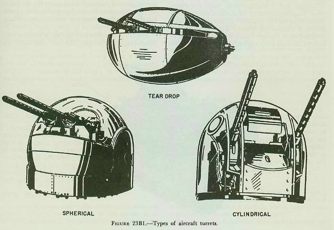
In the ball type of turret, the entire turret moves in train and elevation about axes which intersect at the center of the sphere. Such turrets are suitable for location in the nose, tail, or lower centerline of the aircraft. The cylindrical type of turret moves about its own axis in train, but only its guns and sights move in elevation. Such turrets ordinarily are located in the tail or upper and lower centerlines of the aircraft. The teardrop turret has a streamlined shape, with its axis, which is the chord of the streamlined arc, parallel to the fore-and-aft centerline of the plane. The teardrop type rotates about its own axis in elevation, but only the guns and sights move in train. This type is suitable for waist installation.
In larger airplanes, turrets are installed to provide full defensive coverage. Locations on various planes commonly include the nose, tail, upper and lower deck, and side waist positions. In high-speed planes there is a tendency to sacrifice frontal coverage in favor of good tail coverage, since attack is more probable in the latter area. In smaller planes, fixed, forward-firing guns may be relied upon to provide frontal coverage.
23B3. Fixed and free gunnery
In spite of the rapid development of aircraft rockets and air-to-air missiles, fixed, forward-firing guns are still an important part of the armament of fighter and interceptor planes. They serve as semi-defensive armament on small attack-type planes, and as accessory armament on some larger attack planes when strong gun concentration is desired for strafing. Such guns usually are aligned on the ground by a boresight technique, so that they coincide with the line of flight of the airplane under combat conditions. The angle of attack of the plane varies with its speed and other factors; however, variations in angle of attack within the range of combat speeds usually are not large enough to affect gunfire accuracy seriously.
If time of flight of the projectile were zero, it would merely be necessary to attack at the appropriate speed, point the plane at the target, and score hits. However, since attack angle may vary and the projectile’s time of flight to the target usually is in the order of 1 to 3 seconds, it is ordinarily necessary to make various allowances, such as lead provided to compensate for target motion. Maximum lead is required when the attacking plane is on the beam of the target.
The problem of fire control for free guns is somewhat more complex. This is because the free gun is not aligned with the air stream past the plane, but may take an infinite number of angles thereto. In addition to correcting for target speed and course, it is necessary to correct for own ship’s velocity vector relative to the gun position. The use of simple ring sights (noncomputing) has proved to be fairly effective in fixed, forward-firing gunnery, but is largely ineffective in free gunnery except at point-blank ranges.
23B4. Sights used in aerial gunnery
At the beginning of World War II, noncomputing ring sights and telescopic sights were in common use. They proved to be relatively inadequate, especially in the case of free gunnery, because pilot or gunner had to estimate both range and deflection. Introduction of the illuminated reflector sight partially solved the problem. In this sight a lighted reticle is focused on infinity, and appears superimposed on the target, which is viewed by pilot or gunner through a transparent reflector plate. This sight made it possible to view the target readily, day or night, and permitted unrestricted movement of the head without introducing parallax. But the pilot or gunner still had to estimate his lead.
In the course of World War II, several types of lead-computing sights were developed, all based upon the use of a gyroscopic element to measure angular movement of the line of sight between gunner and target and thus make possible the introduction of the proper lead angle. This type of sight is used on both fixed and free gun mounts. It includes a collimated reflector-type sight, and a gyro-controlled reticle superimposed on a fixed, boresighted reticle. Manual inputs include range and wing span of target. Own altitude, own air speed, and relative angular velocity of the target are computed automatically. Once wing span of the target has been estimated and set in, the gunner keeps the target framed in the gyro-controlled reticle, using his range input to control the size of the reticle. The gunner must keep the target in the reticle and track smoothly, so that gyro precession incident to the tracking, modified by automatic inputs and ballistic corrections, will provide the proper lead. The principle of the lead-computing sight is discussed in chapter 26, the Mark 15 sight described therein being closest in operating detail to those described below and in volume III, chapter 2.
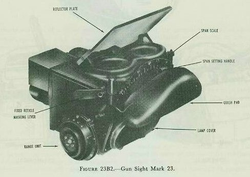
The Gun Sight Mark 23 (see fig. 23B2) is a lead-computing sight designed for use with fixed, forward-firing guns. It omits components which compute windage and the effect of own plane’s motion. It is effective in straight runs, but does not provide for centrifugal-force effects incident to aircraft maneuvers.
A typical lead-computing sight designed for free guns is described in volume III, chapter 23.
23B5. Tactical employment of aircraft guns
The tactical use of aircraft guns differs, depending upon whether primary armament of the plane consists of fixed, forward-firing guns on the one hand, or free guns on the other. Tactical use, however, is not exclusively dependent upon armament. In any case, it is virtually essential that personnel be able to recognize an enemy target as to type, and make a reasonably accurate estimate as to range.
The primary mission of fighter-plane groups often is the interception and destruction of enemy bombers before the latter have opportunity to reach their targets. The situation may be complicated by the presence of an enemy fighter escort for protection of the bombers, which necessitates either an initial attack upon the fighter escort, or simultaneous attack upon escort and bombers. In attacking a bomber, the pilot of a fighter plane with fixed, forward-firing guns is faced by the fact that position at the time the gunnery run is begun is of utmost importance. The plane, pilot, and guns act as one coordinated weapon, which must be properly positioned from the beginning to the end of the run.
Good initial position for attack upon a bomber includes altitude advantage, a location in advance of and to one side of the target, so that the pilot has a good view of the target, and enough maneuvering space to permit turning to close range and arriving at an open-fire point 20° to 30° forward of target’s beam. Such a position is advantageous in intercepting jet bombers when the speed differential between bomber and fighter is small.
The breakaway after an attack should be as rapid and decisive as possible, because during this period enemy gunners have a chance to fire at the fighter plane unopposed. Ordinarily, however, the attack upon a bomber is not made by a single fighter plane, but is a coordinated attack made by several planes. Some of these planes may be able to make firing runs unopposed, because defending gunners are otherwise occupied.
From the standpoint of bomber defense, some advantage is gained by flying in close formation, because fire from several planes can then be concentrated upon a single attacker. Ordinarily the plane commander designates the sector to be covered by each gunner. In most circumstances fire is withheld unless direct attack is made upon own plane, due to the necessity of conserving ammunition.
Fighter-to-fighter combat, if conducted by only two opposed planes, is generally a series of maneuvers designed to gain position in the tail cone of the enemy, where he is undefended. Such encounters put a premium upon airplane maneuverability and pilot skill. The more common tactical approach is coordinated attack by a number of planes designed to take the enemy by surprise, and to establish local, even though temporary, superiority of numbers. Altitude advantage, a position up-sun from the enemy, and a position forward from the enemy, or in the direction he must go to complete his mission, are factors predisposing to success.
C. Aircraft Weapon Systems
23C1. General
Aircraft are used to deliver a large variety of destructive ordnance, including bombs and depth bombs, rockets, projectiles, mines, torpedoes, and guided missiles. To carry this ordnance safely and to deliver it effectively, the aircraft must be provided with a carrying, arming, and launching system that is compatible both with the weapons and with the aircraft itself.
23C2. Weapon compatibility
In any weapon system, the components must be exactly adapted to each other if the system is to function effectively. For example, the carrying lugs of bombs must have exactly the same spacing as the hooks on the bomb rack designed to carry them; and the carrying lugs of rockets must be exactly shaped to fit the rocket launcher. Securing the necessary cooperation between the manufacturers of airframes, armament, and munitions, is one of the most important responsibilities of the material bureaus in Washington.
23C3. Bombing system
A bombing system consists of suspension, arming, and releasing equipment. Bombs are armed and released by mechanical devices, which may be operated either electrically or manually.
Bombs may be suspended from racks mounted on the wings or fuselage, or supported on shackles within the bomb bay. A bomb rack is a permanent or semipermanent structure rigidly bolted to the aircraft. It may or may not be enclosed by a streamlined housing called a pylon. Bomb shackles are nonrigidly suspended from attachments in the aircraft structure. They are used primarily in bomb bays that employ vertical stowage on side rails. When a bomb is released, its shackle swings out of the way, providing clearance for the bomb above. Bomb racks contain integral release and arming devices; bomb shackles depend on other units for control of arming and release.
Bomb racks are carefully designed for compatibility with the bombs they are intended to carry. Bombs are suspended by two lugs spaced either 14 or 30 inches apart. The rack must be strong enough to support the weight of the bomb (from 100 to 2,000 pounds), and to resist the additional stress that results from combat maneuvers. During violent maneuvers, this stress may be many times the weight of the bomb itself.
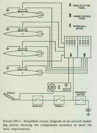
The intervalometer generates electrical impulses that actuate the bomb release units. It may be set for either selective or train release of bombs. When set at SELECTIVE, the intervalometer generates a single release impulse each time it receives an impulse from the bombardier’s firing switch or from the bomb sight. When set at TRAIN, the intervalometer provides a series of evenly spaced impulses. The number of impulses (up to 50), and therefore the number of bombs dropped, is controlled by a dial setting. The impulse frequency can be varied from 2 to 20 per second; it is controlled by matching two dial scales, one of ground speeds and one of distances between the impact points of successive bombs. When the desired spacing is matched with the actual ground speed of the aircraft, a small computing unit automatically sets the proper impulse frequency in the intervalometer.
The bomb-rack release is a mechanical device that releases the bombs by disengaging the bomb-rack hooks from the bomb lugs. The mechanical release is operated by solenoids, which are actuated by impulses received from the intervalometer by way of the bomb selector panel. Operation of the release mechanism is controlled by a mechanical actuator, which may be set to any of three positions: ELECTRICAL ARMED RELEASE (normal operation), SAFE, and MECHANICAL SALVO UNARMED RELEASE.
When the actuator is set at SAFE, no bombs can be dropped. The mechanical salvo position makes it possible to jettison all bombs without arming them.
The station distributor is a specially designed relay switch that distributes impulses from the intervalometer to selected stations in the bomb-release system. Its operation may be controlled by setting a knob pointer to any of 32 dial positions, each of which corresponds to a bomb station. Bombs at any station, or at all connected stations, may be released in train by setting the knob to the dial position corresponding to the first station in the desired train release.
Bomb-arming controls provide for selective arming of bombs. Bombs may be provided with both nose fuzes and tail fuzes, either of which may be armed, as desired. Fuze arming is initiated when an arming wire is withdrawn from it. In the arming control system, a solenoid-operated clamp holds the desired arming wire, so that it will be withdrawn from the fuze as the bomb drops. The wire in any fuze that is not to be armed is allowed to fall with the bomb.
The master armament switch controls the operation of the entire system; when it is open, no bombs can be dropped. Some installations may be provided with either or both of two safety switches; one of these disables the bomb release system when the bomb bay doors are closed, the other when the wheels are down.
Figure 23C1 is a simplified circuit diagram of a typical aircraft bombing installation.
23C4. Rocket systems
An aircraft rocket system, like any weapon system, must be exactly adapted to the requirements of the ordnance it is designed to carry and launch.
Aero 14A and Aero 14B will serve as examples of typical rocket launchers. These are fixed pylon units installed under the wing of the aircraft; the latching, release, and arming mechanisms are contained within an aluminum fairing that bolts to the under side of the wing over a rubber gasket. Each unit is designed to carry and launch 5-inch HVAR rockets, and all 2-lug, 14-inch bombs, up to and including 500 pounds. Rockets and bombs may be released in either the armed or safe condition, by either conventional or toss launching.
The launching mechanism functions electrically, by means of solenoids, to operate linkages that disengage the rocket latches, or release the bomb hooks from their lugs. Rockets are ignited at the instant of launching, through a pigtail wire that plugs into a receptacle in the aircraft wing, aft of the rocket’s tail. The rocket release mechanism contains a shear pin as a part of a safety device. If the rocket motor ignites but the releasing mechanism fails, the pin will shear and release the rocket when its thrust builds up to about 1,500 pounds.
The arming unit will arm the rocket fuze, or either the nose or tail fuze of a bomb (or both bomb fuzes at once if this is desired). The unit is solenoid operated; the mechanism clasps the arming wire of the fuze to be armed; the wire is withdrawn from the fuze, allowing it to arm, when the rocket is launched or the bomb is dropped.
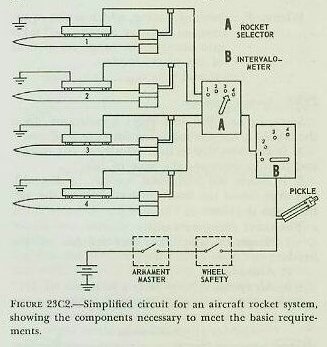
Electrical impulses are channeled to the rocket release mechanism through a station selector. The dial plate and selector knob assembly are mounted on the pilot’s instrument panel. The device may be set to launch rockets or release bombs either singly or in pairs. After the electrical impulse from the firing switch ends, the station selector automatically advances to its next position, so that the ordnance at the next station will be launched on the next impulse. If the firing impulses are provided by an intervalometer, a number of weapons may be launched in train by a single operation of the firing switch.
Figure 23C2 is a simplified circuit diagram of a typical aircraft rocket launching system.
D. Theory of Horizontal Bombing
23D1. General
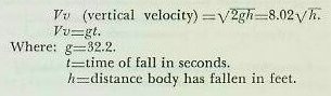
Study of the action of a bomb in air must be started from some situation with which we are familiar. The condition selected for a start, therefore, is the bomb’s action when dropped in a vacuum. The established laws of physics give us formulas for the speed of a falling body, which are expressed in terms of the attraction of gravity and the amount of time or the distance through which it acts. The body will pick up speed or accelerate at a constant rate known as the acceleration of gravity. At sea level this acceleration is about 32.2 feet-per-second per second and is called “g.” The formulas for computing the speed of a falling body in a vacuum are:
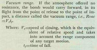
Vacuum trajectory. Due to the fact that a bomb is always dropped from a moving airplane, the bomb in a vacuum would retain, during its time of fall, any horizontal motion imparted to it by the plane, and this motion would remain constant in magnitude and direction. If the aircraft did not alter its course or speed, the bomb would remain vertically below the plane as it fell and the plane would be directly over the point of impact when the bomb hit. The parabolic path that the bomb would follow when dropped from a moving plane is called the vacuum trajectory.
23D2. Range problem
Since, in fact, air does exert a resistance upon the bomb, it has the following important effects:
1. It decreases the vertical velocity at any instant and thereby increases the time of fall.
2. It causes the horizontal velocity to diminish and thus causes the bomb to trail behind the vertical from the plane.
The above effects vary with:
1. Shape, weight, and skin friction of the bomb.
2. Altitude.
3. Air speed.
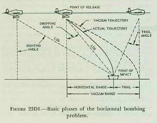
Figure 23D1 illustrates the basic phases of the horizontal bombing problem and shows the difference between an actual and a vacuum trajectory. In using figure 23D1 the following definitions apply:
1. Sighting angle. At any instant the angle between the LOS and the true vertical determined by the bomb sight gyro (spin axis).
2. Dropping angle. The angle between the LOS and the spin axis of the bomb sight at the instant of release. At this instant the sighting angle is equal to the dropping angle.
3. Trail angle. The angle between the spin axis of the bomb sight and the LOS at the time of impact, if the airplane maintains course and speed.
4. Horizontal range in air. The horizontal distance that the bomb travels between release and impact.
5. Trail (T). The horizontal distance between the points of impact of an actual trajectory and a vacuum trajectory.
6. Horizontal range in vacuum. Equal to horizontal range in air, plus trail.

Trail is primarily caused by the horizontal force (air resistance) acting on the bomb after release. Since the bomb is released in the direction of the plane’s motion, the trail is always astern of the aircraft. The amount of trail is dependent upon two factors:
1. The amount of air resistance, which is equivalent to the indicated air speed of the plane at the time of release.
2. The length of time that air resistance acts on the bomb, which is equivalent to the altitude of release.
The actual trail and time of fall values for each type of bomb are determined at the proving ground and appropriate tables are prepared. Trail is always expressed in angular measure (mils) and the amount of trail is called trail angle.
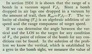
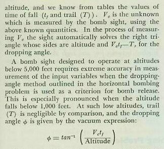
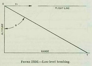
This equation shows the close dependence of the dropping angle on altitude and closing speed. Hence, unless the altitude and closing speed can be held very closely to pre-assigned values, errors in these quantities will produce large range errors on the ground. See figure 23D2.
23D3. Drift problem
Discussion to this point has been based on conditions of either still air or wind that is either up or down the plane’s heading. Since bombing only up or down wind is not practical, the bomb sight is designed to bomb on any course regardless of wind. To do this, means are provided whereby the bomber may direct the pilot to steer a course which will cause the plane’s track to pass through the proper position with respect to the target so that the bomb will hit.
When an aircraft is headed directly up or down wind, it is making good over the ground the course steered. On any other course, with the wind somewhere to the side, the course made good is not that steered, but a resultant of the plane’s course and speed and that of the wind. The angle thus formed between the heading of the plane in the air and its direction of movement over the earth is known as drift angle.
It is obvious that any cross wind will act not only upon the plane but also upon the bomb after release, and compensation must be made. If the bomber were merely to direct the pilot to continuously head the plane for the target, the path over the ground would be constantly changing and eventually the plane would be headed into the wind, the drift angle would be zero, and the plane would pass directly over the target. With such a method the bombing problem is constantly changing and the bomber would never solve the problem correctly.
If the effects of a cross wind could be taken into account and the correct drift angle set up, the approach would be direct and constant, and the dropping angle could then be easily solved.
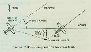
Establishment of the correct drift angle involves the setting up of a collision course with the target. The fact that the plane is flying horizontally above sea level does not introduce difficulties, for we can simply consider the plane’s projection on the surface as being put on a collision course. This method does introduce a small lateral error known as cross trail, but it is compensated for in the bomb sight. This compensation causes the plane to be flown on a track to one side of the target by an amount equal to the value of cross trail. Figure 23D3 illustrates the necessity of compensating for cross trail.
The same consideration for target motion across the plane’s heading is made as was for target motion along the heading in the range problem. It is considered as a cross wind and is absorbed as such in the bomb sight solution.
The solution of the bombing problem is done by the bomb sight in terms of angles rather than distances, and for this reason all values with the exception of altitude are put into the bomb sight as angles in the form of mils; a mil being the angle subtended by an arc whose length is one-thousandth of the range.
The above discussion concerned only horizontal bombing, which serves as a basic model for all types of bombing problems. It also concerned the use of the Mark 15 visual bomb sight. During and since World War II radar sights have been extensively employed. They present one great advantage; namely, that an attack is possible without visual sight of the target. An offset aiming feature in the radar sight makes possible the hitting of a poorly defined radar target by using some other well defined object as a reference point.
In horizontal bombing a compromise must be reached between low and high altitude of attack. Generally, low altitude provides maximum accuracy but gives minimum protection against interception and antiaircraft fire. High altitude gives better protection but less accuracy, and the target must be large enough to be vulnerable over a considerable area.
Horizontal bombing does not place undue stresses on the aircraft structure and therefore the plane is able to carry a comparatively large payload.
E. Other Bombing Problems
23E1. Dive bombing
In dive bombing the plane descends toward the target at an angle of 60 degrees or more, thus imparting considerable vertical velocity to the bomb at the moment of release. In a steep dive, with the bomb released at 2,000 to 6,000 feet, time of flight is short and air resistance, wind, and target motion are small. The problem of obtaining accuracy is simplified and a good percentage of hits can be obtained by use of a simple lead-computing sight. A fixed sight and rule-of-thumb methods may also be used.
The plane makes a good AA target, particularly as it pulls out of its dive. In recent aircraft, structural stresses are not too great and a large payload can be carried. Also advantageous is the adverse psychological effect on enemy personnel.
23E2. Glide bombing
Glide bombing is similar to dive bombing except that the attack angle is less than 60 degrees. This technique is better adapted to fighter-type aircraft which tend to develop excessive speeds in steep dives. Glide bombing is high-speed attack and bombs are released at an altitude of from 2,000 to 3,000 feet. Advantages over horizontal bombing include surprise and quick getaway. The disadvantages are that the bomb velocity is less than in dive bombing and AA vulnerability is greater than in dive bombing.
23E3. Dive or glide bombing
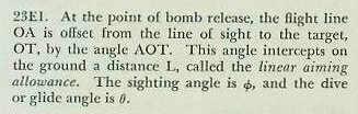
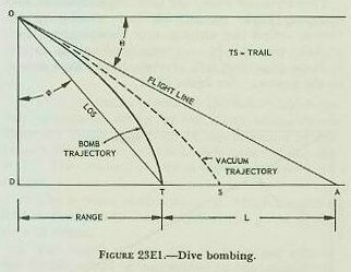
The situation obtained in dive or glide bombing under conditions of no wind is represented in figure 23E1. At the point of bomb release, the flight line OA is offset from the line of sight to the target, OT, by the angle AOT. This angle intercepts on the ground a distance L, called the linear aiming allowance.
23E4. Skip bombing
In skip or masthead bombing the plane usually attacks at less than 500 feet and the bomb is dropped so close to the target that computation is simple and accuracy high. If the target is a ship, the bomb is released to hit near the waterline just before the plane pulls up to pass over the target. Delay fuzes are employed to give the aircraft time to clear the target. Surprise is highly desirable because the plane is exceedingly vulnerable to AA fire.
23E5. Toss bombing
Toss bombing is a technique wherein the pilot dives his plane directly at the target for a short time and then pulls out. The bomb is released automatically during pull-out, the pull-out maneuver giving the bomb additional forward velocity so that it is tossed above the original LOS and its trajectory intersects the original LOS at the target.
Bombs can be released at higher altitudes than with dive or glide bombing. It necessitates only a short bombing run, but the plane is within effective AA range and is vulnerable during pull-out.
In toss bombing, the airplane is flown initially along a collision course, a straight line path containing the target. If the bomb were released enroute, gravity would cause it to fall short. To overcome this difficulty, the pilot pulls out of his straight-line dive and releases the bomb at a precalculated point along this pull-out curve. The essential geometric features of the problem are indicated in figure 23E2.
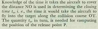
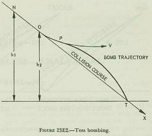
The straight-line dive at the target T, here considered to be stationary, is begun at a point above N; pull-out takes place at O along the curve OP. If the point P is calculated properly and release of the bomb occurs when this point is reached, the bomb trajectory will intersect the target. In the theoretical development we assume the final velocity of the aircraft in the dive to be reached at the point N; and we assume that this final velocity, which we shall denote by V, remains constant along the timing run NO and the pull-up arc OP.
F. Rocketry
23F1. General
The problem of how to aim and fire rockets from aircraft is considerably more complicated than that of aiming and firing bullets. The complications stem mainly from the ballistics of rockets, and from the method of launching them. The two are closely related, since the rocket’s trajectory depends on the way in which it is launched as well as upon other factors.
23F2. Launching airborne rockets
The motion of a rocket can be divided into three distinct periods: the launching period, the period of burning after launching, and the period of motion after burning is over. During the launching period, the rocket is under the influence of the aircraft that carries it. During the burning period, the rocket is subjected to the force of gravity, jet forces, and aerodynamic forces. After the rocket fuel is consumed, the rocket moves under the influence of gravity and aerodynamic forces only, and its behavior is then similar to that of a bomb.
Most airborne rockets are fin-stabilized in the same manner as bombs. The trajectory of such rockets differs from that of bullets in three respects: (1) rockets are slower; (2) rockets tend to follow the flight direction of the aircraft, while bullets travel in the direction of aim of the gun; and (3) the rocket trajectory has an appreciable curvature. These three characteristics have considerable influence on the aiming problem. Since we have a longer time of flight, greater allowance for target speed and wind must be made; and, in addition, the greater curvature of the trajectory means larger gravity drop allowance.
Since the rocket tends to follow the direction of flight of the aircraft, its trajectory is highly dependent on the manner in which it is launched. Thus the launching device, the method of stabilization (whether fin- or spin-stabilized), and the attitude of the aircraft at the instant of launching, all contribute to the aiming problem.
23F3. Factors affecting rocket trajectory
Three factors strongly affect the trajectory of rockets: gravity, dive angle, and launching speed.
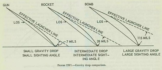
Figure 23F1 shows the difference in magnitude of the gravity drop effect for shell fire, rocket fire, and bomb dropping; it illustrates the intermediate role of the rocket.
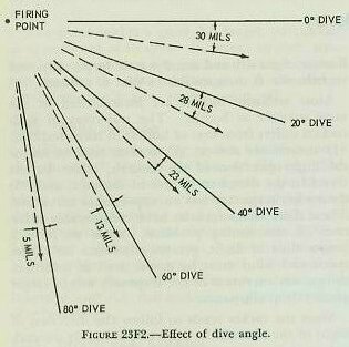
Figure 23F2 shows the effect of the dive angle on the trajectory drop, and illustrates the fact that the trajectory drop decreases as the dive angle increases. Trajectory drop is the angle between the effective launching line and the line of sight at the point of release.
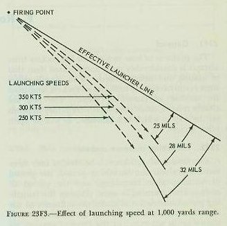
Figure 23F3 shows the effect of launching speeds on the rocket trajectory, and illustrates the fact that the greater the speed the smaller the trajectory drop.