
Chapter 22 of Naval Ordnance and Gunnery, Volume 2 — Fire Control covers naval gunfire support: the use of a ship’s guns to support troops ashore in amphibious operations. It traces the mission, advantages, and limitations of naval gunfire support, the standard terminology, the selection of weapons and projectiles, the phases of support before, during, and after a landing, the special problems of firing at land targets, the Military Grid Reference System for designating targets, and spotting by the target-grid system.
A. General
22A1. Historical introduction
In the course of World War II, naval task forces frequently carried out bombardments of enemy installations on shore. After the ineffective results noted during the Tarawa operation in November 1943, shore bombardment techniques were gradually improved and refined through successive landings at Roi-Namur, Eniwetok, Saipan, Guam, Peleliu, the Philippines, Iwo Jima, and Okinawa. Later, the Korean conflict gave frequent opportunity for the application of the techniques learned in World War II; in particular, the use of naval gunfire to support the landing of troops on defended enemy territory.
Opposed amphibious landing is one of the most hazardous types of military operation. Until World War II, many military authorities believed that such an operation was too hazardous to be attempted. This belief was based largely on the British experience at Gallipoli, in World War I. This operation failed, largely because of the absence of organic supporting arms prior to, during, and immediately after the landing. The value of naval gunfire support rests principally on its continuous availability during these critical periods.
22A2. Mission of naval gunfire support
The mission of naval gunfire in support of landing operations is to aid the seizure of the objective by reducing or neutralizing shore installations and troops that oppose our forces prior to and during the landing, and by assisting the advance of our troops after the landing has been made. This support is vitally important in the period after the troops have landed but before adequate artillery can be brought into action. To be successful, naval gunfire support for amphibious operations must be carefully planned in advance, and must be executed with skill and dispatch. Full exploitation of support can be achieved only if ground, naval, and air personnel understand the organization, basic techniques, capabilities, and limitations of naval gunfire support, and follow the standard procedure which has been agreed upon by the joint services.
Naval gunfire is delivered from ship’s batteries not only in support of troop operations, but of related naval and air operations, such as mine warfare activities, air-sea rescue operations, reconnaissance and demolition operations, demonstrations, feints, raids, flak suppression during air strikes, and interdiction of coastal roads, railroads, airfields, and troop assembly areas. All these activities rest on the same basic principles as the naval gunfire support of amphibious operations.
The basic task of naval gunfire support units in an amphibious operation is to support the seizure of the objective by destroying or neutralizing:
1. Shore installations that oppose the approach of ships and aircraft to the objective.
2. Defenses that may oppose the landing.
3. Defenses that may oppose the post-landing advance of the troops.
These tasks are carried out in the preparation of the objective for the landing, the support of the landing, and in post-landing support.
22A3. Advantages of naval gunfire for troop support
Naval gunfire has many capabilities for troop support in landings which are not possessed by artillery. The principal ones are:
1. Availability. Gunfire support ships are continuously available before, during, and after the landing, as long as the zone of action ashore is within the range of the ship’s guns.
2. Mobility. Within the limitations of navigation, ships can move rapidly from one area to another as the situation ashore develops. At the same time, the most favorable ranges and lines of fire can be fully exploited, and enemy counterfire can be evaded.
3. High rate of fire. Power loading and mechanical ammunition supply make it possible to deliver a large volume of fire in a short time. This characteristic is of great value in neutralization missions.
4. High muzzle velocity and flat trajectory. Naval guns, particularly those of heavy caliber, have great penetration and destructive power, especially against installations presenting vertical surfaces.
5. Small deflection pattern. The comparatively small dispersion in deflection of naval guns makes them valuable for close support of troops when the line of fire can be made parallel to the troops’ front line (enfilade fire).
6. Variety of weapons and types of ammunition. Calibers of guns range from 20-mm to 16-inch, with ammunition of many types, including armor-piercing, fragmentation, and reduced-charge. Other available weapons include rocket and guided missile launchers, with a wide variety of ammunition types for each.
22A4. Limitations of naval gunfire for troop support
The tactical employment of naval gunfire in support of troops has certain limitations, which must be taken into consideration in both planning and operational stages. The most important limitations are:
1. Necessity for observation. Naval gunfire, except for area fire on very large targets, must be observed and corrected to be effective. This requires a spotting agency, such as a ground spotter, air spotter, or shipboard spotter.
2. Navigational limitations. Ships are forced to remain in safe, navigable, mine-free waters, and therefore sometimes cannot take advantage of the positions most favorable for the attack of targets. In some cases, ships cannot fire at all on certain defiladed (located on a reverse slope) targets. Obviously, the maximum range inland is limited by the position of the ships, as well as by the characteristics of the weapons used. Further, the fact that the ship is in motion requires the continuous and accurate fixing of the ship’s position for delivery of fire on targets not visible from the ship.
3. Communications limitations. Radio and visual communications between ship and shore are not as flexible, reliable, or secure as communications by wire or telephone.
4. Limitations of pattern. By comparison with artillery, naval guns have a small deflection pattern, a large range pattern, and a flat trajectory. This is an advantage in some respects, but requires careful selection of lines of fire when engaging targets near our own troops. The difficulty of fire against defiladed targets may be overcome by using reduced-velocity charges or by increasing the range, to obtain a greater angle of fall.
5. Limited ammunition capacity. The limited capacity of the ship’s magazines, coupled with the fact that a ship must always retain a certain amount of ammunition for its own protection, restricts the ability of any one ship to maintain uninterrupted support over an extended period of time. This disadvantage may be overcome by providing adequate ammunition replenishment and by rotating ships assigned to support missions.
22A5. Terminology
Naval gunfire may be classified in various ways, as shown in the following paragraphs. The classifications in use are interrelated, making it necessary to employ terms from several types of classification for a full description. These classifications are made with respect to:
1. Effect sought:
a. Destruction. Deliberate and accurate fire, usually delivered at short range, for the purpose of destroying a target, usually a material object.
b. Neutralization. Rapid, fairly accurate fire delivered for the purpose of hampering, interrupting, or preventing enemy fire, movement, or action. The destruction of weapons and personnel is a secondary consideration. The effect of neutralization is comparatively temporary, and such fire may have to be repeated.
c. Maximum damage. Fire against a target which is desired to be destroyed, but which probably cannot be completely destroyed without excessive ammunition expenditure, because of its size, location, range, or lack of vulnerability to naval gunfire.
2. Tactical use:
a. Close supporting fire. Gunfire delivered on enemy targets which, because of their proximity, present an immediate and serious threat to the supported unit.
b. Deep supporting fire. Gunfire delivered on objectives not in the immediate vicinity of friendly forces, for the purpose of neutralizing or destroying enemy reserves and weapons and interfering with enemy command, supply, communications, and observation.
c. Harassing fire. Sporadic fire delivered during otherwise quiet periods to prevent enemy rest, recuperation, or movement, and in general to lower enemy morale and combat efficiency.
d. Interdiction fire. Fire designed to prevent or curtail the use by the enemy of an area, bridge, defile, airfield, route of communication, or the like.
e. Illuminating fire. Gunfire employing star shells to illuminate the enemy, to detect his movements, to aid our own observation, or to facilitate own troop movements.
f. Preparation fire. A heavy volume of prearranged neutralization fire, delivered just prior to a landing or a ground attack by friendly forces on enemy positions.
g. Counterbattery fire. Gunfire delivered against active enemy guns and fire control stations for the purpose of silencing the guns.
h. Screening fire. Gunfire employing smoke projectiles, delivered to obscure the enemy’s vision of friendly units and their deployment, movement, or maneuvers.
3. Degree of prearrangement:
a. Prearranged or scheduled fire. Gunfire that is formally planned and executed against targets of known location. Such fire is usually planned well in advance and is executed at a predetermined time or during a predetermined period of time.
b. Call fire. Gunfire delivered at the request of troop units ashore, or of some spotting agency. Call-fire missions must not be interrupted without permission of the unit requesting the fire, except in case of emergency.
c. Opportunity fire. Gunfire delivered without formal planning or troop request on newly discovered targets, or upon targets of a transitory nature. Targets of opportunity may present themselves to the firing ship at any time, but fire must not be delivered without due regard for the safety of friendly troops. Ships delivering fire on targets of opportunity in close proximity to own troops require the approval of the troop echelon concerned before opening fire. Ships executing deep support missions must assure themselves that the target of opportunity is within their assigned sector of responsibility.
4. Technique of delivery:
a. Direct fire. Gunfire delivered on a target by using the target itself as a point of aim for laying the guns or director.
b. Indirect fire. Gunfire delivered on a target which is not itself used as a point of aim for laying the guns or director. Direct fire is usually used on targets which can be seen (by optics or radar) from the firing ship; indirect fire is always used on targets not visible from the ship.
5. Type of fire:
a. Area fire. Gunfire delivered in a prescribed area. Area fire is generally neutralization fire.
b. Point fire. Gunfire directed at a definite material target in order to destroy that particular object.
c. Defilade fire (reverse-slope fire). Gunfire delivered on targets located behind some terrain feature, such as a hill or ridge, which masks the target.
d. Enfilade fire. Gunfire delivered on a target in such a manner that the range pattern of the fall of shot coincides with the long axis of the target.
Some other general terms used in naval gunfire support operations are:
1. Amphibious Task Force (ATF). A task organization under naval command composed of assault shipping, embarked troops, and supporting naval units and tactical air units.
2. Amphibious Troops (AT). The troop elements assigned to an Amphibious Task Force.
3. Advance Force. A task organization of ships which conducts operations such as reconnaissance, minesweeping, underwater demolition, diversionary raids, and preliminary bombardment prior to the arrival of the main body of the ATF in the objective area.
4. Attack Force. A subdivision of an ATF consisting of assault shipping with embarked troops and supporting naval and tactical air units, operating to establish a landing force on shore and support its operations thereafter. In an operation involving only one Attack Force, it is also the Amphibious Task Force.
5. Fire Support Group. A group of ships, part of the Attack Force, assigned the mission of naval gunfire support of an amphibious operation.
6. Objective Area. A defined geographical area within which is located the objective to be captured or reached by the military forces.
7. Objective. A physical area or location on the ground, usually a readily identifiable terrain feature, which a troop unit is assigned to capture or occupy. Objectives may be designated as intermediate or final objectives.
8. D-Day. The day on which an amphibious landing takes place.
9. H-Hour. The actual time to the minute at which the leading wave of the landing force touches down on the beach; if the actual H-hour differs from the scheduled H-hour, the actual time of H-hour is broadcast to all ships and troop units by the Amphibious Task Force Commander.
10. Zone of Responsibility. The land in the objective area is divided into zones which are assigned to fire-support units or to individual ships which are responsible for observing, destroying, or neutralizing known enemy installations and for attacking targets of opportunity therein. A ship may fire in its own ZR without clearance from any troop unit. These zones include all land area in the vicinity of the landing forces except the Close Support Area.
11. Close Support Area. The area between friendly front lines and the near limits of Zones of Responsibility. Support ships may fire into these areas only upon call from supported troop units, or after receiving clearance from the troop unit concerned to fire on a specific target.
12. Preliminary Bombardment. Bombardment in the objective area delivered by an Advance Force prior to arrival of the main body of the ATF, with the primary purpose of destroying enemy defenses which might hinder or abort the landing.
B. Naval Gunfire Support Operations
22B1. Selection of the weapon
Selection of the gun or weapon to be used in naval gunfire support is determined by the nature and size of the target to be engaged and by the proximity of friendly troops to the target. The 5-inch gun is normally used for close supporting fire; its rapid rate of fire and relatively small pattern size make it an excellent weapon for neutralization and destruction of targets immediately in front of advancing troops. Destroyers are usually assigned close supporting-fire duties because their maneuverability permits them to shift positions easily and quickly and to take positions close inshore for direct fire on targets in coastal areas.
Guns of 8-inch and larger caliber, with their great accuracy at long range, are normally reserved for deep supporting fire. The lethal bursting radii of projectiles from these guns limit their employment in close support. Moreover, ships mounting these guns (battleships and cruisers) are hampered in responding quickly to fire commands because they are less maneuverable than destroyers and their fire control organization is more complex. The larger ships also have to carry out a number of additional duties. The destructive power of the projectiles of large-caliber guns makes them particularly effective against heavy installations ashore.
The 6-inch gun has qualities suitable for either close or deep support, but the light cruisers mounting these guns are better adapted for deep support use, since their maneuverability is restricted.
The 3-inch and 5-inch guns of DE’s, APD’s, DM’s, and DMS’s are suitable for harassing fire missions of the sort often executed against areas remote from our own troops, such as towns, harbors, and coastal air strips. The use of these ships for this purpose provides a necessary feature of support and releases ships with more accurate fire control equipment for use where precision fire is required.
40-mm guns are effective for area neutralization where heavier caliber guns are not required. The fire control installation used with these guns is inadequate for indirect fire or safe close supporting fire. These guns are particularly effective against shoreline targets, especially enemy personnel in caves. When such fire is controlled by the dual-purpose gun directors, it is accurate and effective at short ranges; when not so controlled, larger safety limits with respect to proximity of own troops must be allowed.
22B2. Specialized fire-support ships
The support of troops in landing operations has brought forth many new special weapons and specialized fire-support craft. The most important among these are:
1. The LSMR. This is primarily a rocket ship; its main armament consists of launchers for 5-inch spin-stabilized rockets, the maximum range of which is about 11,000 yards. This craft can be used for deep support, harassing, and neutralization fire as well as for beach neutralization. Because it is equipped with a rocket fire control installation, it can use its fire somewhat closer to own troops than the rocket LCS, which lacks this advantage.
2. Inshore fire-support ship (IFS). The inshore fire-support ship, a recent addition to the fleet, is designed for providing close support to troops in amphibious landings. The major armament consists of rapid fire rocket launchers. A crew of 162 will man this 245-foot vessel, whose twin screws are powered by diesel engines. The displacement of the ship is 1,500 tons.
22B3. Projectiles and fuzes
The selection of the projectile type to be used in support of troops depends upon the type of target and the effect sought on that target. High-capacity (HC) projectiles are designed especially for use in shore bombardment. They have a great explosive content at the expense of penetrative ability and produce a heavy blasting and shrapnel effect. HC is therefore suitable for neutralization or for destruction of relatively light installations. Antiaircraft common (AAC) projectiles are similar to HC projectiles in explosive and penetrative qualities. Their effective bursting radius of 35 to 50 yards makes them most satisfactory for close-support neutralization fire. Armor-piercing (AP) and common (COM) projectiles are designed to penetrate armor plate before detonating. Their use in shore bombardment is limited to fire on fixed enemy defenses such as concrete pillboxes and blockhouses which cannot be reduced by HC projectiles. White-phosphorus (WP) projectiles have been found very useful for screening, incendiary, and antipersonnel effect. They may also be used as identifying or marker shot to identify salvos, to permit spotting when the impact burst is invisible due to foliage, or to give a prearranged signal to the troops supported. Illuminating (Illum) projectiles are used to provide illumination only.
The type of fuzes used with HC, AAC, and WP projectiles may be varied to meet different objectives. Mechanical time fuzes may be used to provide air bursts for maximum effect against personnel and light equipment. They should be set to burst 25 to 50 feet directly above the target. Proximity fuzes accomplish the same purpose with greater accuracy and less difficult fire control, as they compensate automatically for variations in ground elevation. Point-detonating fuzes, like proximity fuzes, require no advance setting but produce a lower and more concentrated burst, often desirable for demolishing equipment. Base-detonating fuzes are, of course, required whenever armored or other heavy structures must be penetrated.
22B4. Phases of support
It is convenient to divide the support for a landing operation into three general phases as follows:
1. Pre-landing bombardment. This phase, which may commence well in advance of D-day, utilizes quick raids by surface ships to inflict damage and cause confusion, after which the ships retire. Similar strikes may be carried out by aircraft during this phase.
More often the bombardment group will move into position a few days prior to D-day and commence its schedule of prearranged fire which may continue right up to H-hour (the time of landing of the first wave of troops) or may be interrupted by retirement of the bombardment group for reasons of safety.
During this period, the effect sought by the bombardment is destruction of beach defenses, gun control and observation posts, or any defenses which could effectively oppose the landing. Slow, deliberate, close-range destructive fire is used whenever it is possible. In this, as well as in later phases, an attempt is often made to conceal the actual landing beaches by a schedule of fire covering other areas. The number of ships engaged in the pre-landing bombardment, its duration, and the type of ammunition expended will depend upon such factors as the number of ships and planes available, the logistics (especially ammunition supply), and the nature of the terrain and its defenses.
In addition to its primary purpose of destroying designated targets which may hamper the landing, the force is often called upon to provide cover for minesweepers, underwater demolition teams, and hydrographic survey vessels. During the night it may engage in harassing fire to break down enemy morale. During the last hours prior to H-hour it may be called upon to provide interdiction fire to prevent assembly of reinforcements and their movements into the area of the landing beaches to man installations or repair damaged equipment. On D-day, prior to embarkation of troops, the bombardment of strong resistance points will be intensified. The force may be called upon to cover the final mine sweeping operations and the approach of the attack force, especially the transports. When the transports are in position and the landing beaches are disclosed to the enemy, fire can be concentrated on strong points which intelligence reports or observation indicate have not been destroyed.
During this period, also, air strikes are often scheduled to bomb and strafe the beaches. Provisions must be made to control fire so as to avoid hitting friendly planes.
2. Support during the landing. The primary missions of naval gunfire in this phase are to protect the transports while the landing force is embarking in boats, to silence batteries which might destroy the assault waves as the boats move in to the beach, and to cover the actual landing of troops. The barrage must be lifted inland or shifted to the flanks as the troops near the beach to avoid hitting the landing force as well as to neutralize strong points from which destructive crossfire could be poured on the beaches. In addition to close supporting neutralization fire on the landing and adjacent areas, deep supporting fire must be concurrently delivered to prevent enemy troop movement toward the landing area and to neutralize more remote opposing enemy defenses.
During the last few minutes, as the first wave nears the beach, a final air strike often parallels the beach, strafing and driving the enemy to cover. Also just before the landing, the rocket and mortar ships close inshore will deliver a devastating barrage, saturating the whole beach area.
The rapidity of events and general lack of information from troops being supported during and immediately following a landing require that most of the supporting fire be planned in advance, for delivery according to a carefully formulated and coordinated time schedule.
It is essential that close and deep supporting fire be scheduled to continue after the landing, in order to neutralize enemy opposition which would hinder the rapid establishment of organized troop units ashore. The post-landing schedule of fire must be carefully planned for coordination with the estimated troop advance ashore, but must be capable of quick modification to permit repeating, extending, or discontinuing any portion of the schedule when the advance differs from that expected. The duration of the scheduled fire after H-hour must extend well beyond the estimated time required to establish effective naval gunfire control agencies ashore.
In the case of heavily defended objectives, scheduled fire for close support must continue at least an hour after the landing, and for deep support at least 4 hours.
3. Support for troop advance ashore. Naval gunfire is employed after the landing phase to assist the advance of troops to their final objectives. Close supporting fire from ships assigned to them, daily or upon special request, is made continuously available to troop units in assault. Deep support, including daily destructive fire missions, preparation fire for troop attacks, and night harassing fire, are scheduled for daily execution in fulfillment of troop requests. This phase of naval gunfire support commences upon the completion of the prearranged scheduled fire in support of the landing and continues until naval gunfire is no longer required for support.
22B5. Land-target problem
Naval gunfire against targets on land offers essentially the same problem as firing at a ship dead in the water, except for the following additional considerations:
1. Ship’s position. As mentioned before, the geographical position of the firing ship must be continuously and accurately fixed, as from this are determined the range and bearing of the target in many instances when indirect fire must be used.
2. Terrain. Terrain features make correction of the fall of shot a difficult problem. Since range tables and rangekeeper solutions in main-battery systems assume the point of fall to be in the horizontal plane, the elevation of the target above sea level must be compensated for in the fire control solution.

Figure 22B1 illustrates the errors resulting when the range of a land target is taken from a chart and the target’s elevation is not considered. When dual-purpose guns are used for shore bombardment, the antiaircraft fire control systems provide a ready solution to this problem. Terrain features also affect the size of the pattern in range; a forward slope decreases it, and a reverse slope increases it.
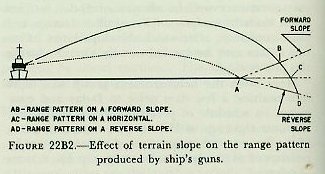
Figure 22B2 illustrates these effects.
3. Current effects. The set and drift of the current will affect the solution of the fire control problem. When determined, drift may be entered into the rangekeeper or computer as target speed; the direction of the set is reversed and introduced as target course.
4. Parallax. In order to cover area targets more effectively with the shots of individual salvos, it may be desirable to increase the deflection pattern by setting the horizontal parallax correctors at infinity (i.e., removing horizontal parallax correction from the gun battery).
5. Varying ammunition. Frequent and rapid changes in the targets to be engaged require ready accessibility of various types of ammunition and fuzes.
6. Principles of employment. Effective support of troops by naval gunfire is dependent on certain principles of employment and techniques of delivery of that gunfire which might be called tricks of the trade. The following paragraphs briefly discuss these. Prerequisites of effective support are the proper alignment of the fire control system and gun battery, rapid and reliable internal and external communications, and well-trained ship control, fire control, and gun control personnel. The primary duty of naval gunfire in all phases of the support is the immediate and effective silencing of heavy enemy weapons which open fire on our forces. It is essential that a counter-battery plan satisfying all contingencies be kept in constant readiness and that fire-support ships be ready and alert at all times for the delivery of this fire. When the source of enemy fire is not known, heavy counter-battery fire on suspected sources is delivered pending the determination of the exact location of the enemy battery. The whereabouts of friendly forces must be kept in mind during such an attack.
Only by thorough familiarity with the land areas assigned, achieved through repeated firing, observation, and analysis, can the most effective fire be delivered by ships. The shifting of ships to different areas of responsibility, or frequent shifting of fire between targets widely separated in the same general target area, is avoided.
Unlike surface or air actions at sea, naval gunfire support requires moderately low speeds. The use of high speed in a firing ship requires it to make frequent course reversals in order to remain in its assigned sector, results in unacceptable inaccuracies in establishing the ship’s position for indirect fire, takes the ship too quickly beyond effective firing positions limited by terrain features, and may result in prohibitive interference with other activities offshore. A low speed is usually selected which will allow good control of the ship and the supporting fire, consistent with the tactical situation and the submarine menace. If necessary, the ship will lie to or anchor, maintaining desired heading by the use of the engines. Best results for indirect fire will be obtained if ships steam on a steady course at a constant low speed.
Direct fire is employed whenever possible, although indirect methods must always be employed when visible points of aim are not available. Indirect fire requires more ammunition and time than direct fire for equally destructive success. It requires air or ground observation of the fall of shot in order to ensure hits on point targets. The effectiveness of naval gunfire is increased by the employment of an air spotter working with a ground spotter.
Once established, the maintenance of the hitting gun range and deflection is essential to effective destructive fire. Periods of continuous slow fire with reduced salvos are therefore preferable to more rapid fire interspersed with relatively long non-firing intervals.
The decisive destruction of heavy defenses is greatly enhanced by very close-range, slow, deliberate, direct fire against such installations. Fire-support ships usually operate as close inshore as safe navigation, the tactical situation, enemy shore batteries, and the type of fire required will permit. Close supporting neutralization fire on the landing area in support of troops about to land, although scheduled to be shifted thereto on a time basis relative to the estimated time of H-hour, must be adjusted according to the actual position of the troop landing craft. From reports of landing-craft progress received, but primarily from own observation when possible, fire-support ships individually determine when their fire is about to endanger troops nearing shore, and accordingly shift the fire from the landing area.
Close cooperation between ships and the troop units to which assigned for support is essential for maximum effectiveness. Interchange of information between supporting ships and troop units results in more intelligent and effective fire support. Of particular importance in this connection is the safety requirement that all fire-support ships maintain an up-to-date plot of own troop front-line positions as periodically announced by elements of the landing force. This not only prevents endangering own troops, but permits selection of the most suitable line of fire with respect to troop lines. Another consideration is the necessity for safeguarding friendly aircraft operating in the area.
Illumination of land areas by naval star shells is effective in preventing enemy counterattacks, infiltration, and the movement of enemy troops at night. Its morale-boosting effect on our own troops generally results in requests for exorbitant star-shell expenditures to produce unnecessary illumination of the land area throughout the night. Except during actual enemy counterattacks, star shells fired at a reduced rate and at irregular intervals normally discourage enemy movement. Maximum benefit from the limited supply of star shells available requires judicious control and coordination by troop units to avoid silhouetting of own forces ashore and afloat. When delivering illumination fire, the line of fire must be so adjusted with relation to our front lines that friendly troops are not endangered by star-shell bodies. Except in rare instances, searchlight illumination for troop support is generally unsuccessful; it almost invariably draws enemy fire on the ship employing it.
7. Requirements for neutralization. The volume of fire required for neutralization of an area is difficult to establish. The standard volume established prior to World War II prescribed the equivalent of sixteen 75-mm projectiles per minute per 100-yard square as being sufficient for neutralization. Although the experiences of World War II showed this to be entirely inadequate in many instances, it is still a valuable guide which may be modified as conditions dictate. Experience proved that the blast effect of bursting projectiles had been highly overrated in neutralizing effect; it was found instead that neutralization primarily depended upon the casualties produced or threatened by flying fragments. Fragmentation effects vary greatly, even in the case of projectiles which are identical, because they depend upon such factors as angle of fall and terminal velocity. For example, the number of casualties inflicted may double with an increase in angle of fall from 100° to 60°. The effectiveness of fire for neutralization will also vary in accordance with the terrain, the types of enemy installations, and the quality of the enemy troops. Extensive studies of neutralization effects in World War II are being made in an effort to establish a new and more accurate neutralization factor.
8. Target intelligence. Before undertaking any bombardment of land targets, a thorough familiarity with the terrain and hydrographic features of the objective, and with the location of profitable targets, must be acquired. The study of available charts, maps, aerial photographs, radar PPI simulations, mosaics, and other pertinent information will be necessary for rapid, effective troop support. Normally these charts, maps, photographs, and target information will be furnished each fire-support ship prior to the operation. The systematic destruction of defenses requires the continuous assembly and evaluation of targets known beforehand, and of those discovered in the course of the operation. Damage assessment must be based upon visual observation and photo-analysis. A common error is over-optimism as to the effectiveness of naval fire against land targets.
9. Military Grid Reference System. Rapid and accurate means for designating the location of targets is an essential feature of naval gunfire support. It should be obvious that the troop unit supported and the supporting ship must use a common map. Although they need not be of the same scale, and seldom are, the target maps must be identical regarding terrain features and the method of locating points thereon. Like other techniques of naval gunfire support, the development of a system of target location designations has passed through several stages, following generally a grid-system method. In this method, the land and sea areas at the objective are divided into squares by north-south and east-west lines, which are numbered. These lines are called grid lines.
The Military Grid Reference System imposes vertical and horizontal reference lines over a projection of the earth’s surface. Its purpose is to simplify and to increase the accuracy of reporting and plotting in military operations. The grid reference system is based on two projections: the Universal Transverse Mercator (UTM), and the Universal Polar Stereographic (UPS).
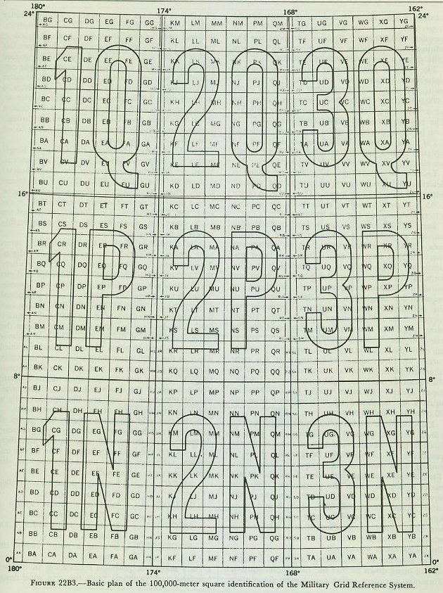
a. Universal Transverse Mercator. Any projection is simply a method of depicting a spherical surface on a flat piece of paper. The familiar Mercator projection, long used in navigational charts, mathematically develops the surface of the earth on a cylinder which is tangent to the earth’s surface at the equator. The Transverse Mercator uses the same principle, except that the cylinder is tangent to the earth’s surface along the great circle of a meridian, at right angles to the equator. In the UTM, both meridians and parallels appear as slightly curved lines. See figure 22B3. There is very little distortion near the line of tangency, so that a relatively narrow band of longitude can be accurately shown from pole to pole.
Universal Transverse Mercator coverage is based on five separate spheroids which depict the earth from 80° south latitude to 80° north latitude. The spheroids are mathematically corrected to allow for the irregularities of the oblate spheroidal shape of the earth. When pieced together, the spheroids join each other on exact degrees of latitude and on exact even degrees of longitude.
Between latitudes 80° N and 80° S, the UTM grid divides the earth into areas 6° east-west by 8° north-south. Columns (6° wide) are numbered 1 through 60 consecutively, starting at the 180° meridian and proceeding easterly. Rows (8° high) start at 80° S and proceed northerly to 80° N. They are lettered alphabetically C through X, omitting letters I and O.
The method of identifying the 6° by 8° areas is called grid zone designation. Grid zone designation for any area established by the columns and rows is determined by reading right-up on the chart. As an example, column designation 2 and row designation P produce grid zone designation 2P.
Each grid zone designation is subdivided into 100,000-meter squares, as shown in figure 22B3. The 100,000-meter squares are also laid out in columns and rows, but these are identified by letters only.
As shown in figure 22B3, the 100,000-meter squares are lettered without regard for boundaries of separate grid zones. Columns are lettered A through Z (omitting I and O) beginning with the 180° meridian and proceeding east along the equator. Since the 100,000-meter squares are established about the central meridian of each zone, UTM projection creates partial squares at the edges of each zone. The partial squares create partial columns which are included in the alphabetical progression just as though they were made up of complete 100,000-meter squares. In lettering the columns, the alphabet is repeated every 18°. Figure 22B3 shows a complete cycle of lettering.
The rows of 100,000-meter squares are lettered alphabetically from south to north, A through V, omitting I and O. The alphabet is repeated every 2,000,000 meters (20 squares). Squares having the same identifying letters are separated as follows: the row alphabet for each odd-numbered UTM zone begins at the equator; for each even-numbered UTM zone, it begins 500,000 meters south of the equator. Thus, squares carrying the same letters are effectively separated by 18° of longitude.
Location of a particular 100,000-meter square is determined by reading right-up, first the column letter and then the row letter. Thus, MT in figure 22B3 is found by reading right along the column letters to M and up the row letters to T.
Each 100,000-meter square is further divided to provide, eventually, a 100-meter square reference area. First, grid lines spaced 10,000 meters are placed within each square. Lines are placed vertically and horizontally so that their intersections form right angles. Since the grid lines form one hundred 10,000-meter squares, only two digits are required for designation, 00 to 99. Designation of the 10,000-meter squares begins in the lower left corner of the 100,000-meter square. The 10,000-meter square in this corner is designated 00; the one immediately above is 01, the next 02, and so on until the top square in the upper left corner carries 09. The square immediately to the right of square 00 is 10, the next is 20, and so on to 90, the square in the lower right corner of the 100,000-meter square. In other words, the 10,000-meter squares are numbered up each column from the 00 column to the 90 column.
Each two-digit 10,000-meter square is further divided into 100 squares by placing grid lines at 1,000-meter intervals, vertical and horizontal, perpendicular at the crossings. Designation of the resulting 1,000-meter squares requires four digits. Two of the four digits are taken from the 10,000-meter square in which the particular 1,000-meter square is located. For example: in the 1,000-meter square designated 6957, digits 6 and 5 are keyed to the 10,000-meter parent square, 65. Figure 22B4 shows the location of area 6957 within square 65. Actually, area 6957 is square 97 within the 10,000-meter square 65.

For accuracy in pinpointing targets, it is necessary to break down further the 1,000-meter squares. Formerly, a system called target area designation (TAD) was used for this purpose. Each 1,000-meter square was divided by grids at 200-meter intervals, making twenty-five 200-meter squares, labeled A through Y. The lettering started at the upper left corner of the square, and the alphabet progressed row by row across, finishing at the lower right corner of the square. Under this system, a 200-meter square could be designated by adding the letter to the four-digit 1,000-meter square. For greater accuracy, the individual 200-meter square was broken down into areas designated by numerals 1 through 5, providing enough accuracy for the spotter to adjust salvos to hit the target.
The U.S. Navy Hydrographic Office no longer prints the 200-meter grid lines, the TAD instructions, or the letter designation for the 200-meter squares on grid charts. Since this is fairly recent policy, charts bearing this system will probably be issued until the present supply is exhausted. However, the TAD system is no longer authorized for U.S. Navy use, and reference to it on available charts is to be ignored.
The authorized method for reducing the reference area to a 100-meter square requires six digits. To illustrate, consider the previous example where the 1,000-meter square was 6957. Adding two digits divides this area into tenths, or 100-meter squares. Thus, in the designation 693578, the two additional digits (3 and 8) mean three-tenths (300 meters) east from the southwest corner of the 1,000-meter square 6957, and eight-tenths (800 meters) north from the southwest corner of the square. The east distance is always placed between the second and the third digits of the 1,000-meter designation, and the north distance is placed at the end. In the final figure, 693578, observe that the first three digits indicate distance east of the southwest corner of the original 100,000-meter square, and the last three digits indicate distance north of the southwest corner.
A military grid reference consists of a group of letters and numbers which indicate (1) the grid zone designation, (2) the 100,000-meter square identification, and (3) the grid coordinates; that is, the numerical reference of the point expressed to the desired accuracy. Examples:
52SCU locating a point within a 100,000-meter square.
52SCU65 locating a point within a 10,000-meter square.
52SCU6957 locating a point within 1,000 meters.
52SCU693578 locating a point within 100 meters.
As a matter of practical referencing in a shore bombardment problem, both the grid zone designation and the 100,000-meter square identification are generally omitted. The grid reference box shown as a part of the marginal data of every chart specifies the maximum distances beyond which omissions in reporting are not permitted.
b. Universal Polar Stereographic. The projection used for the polar areas is the polar stereographic, covering the limits from 80° N to 90° N for the north polar area, and 80° S to 90° S for the south polar area. The system for gridding the poles is called the Universal Polar Stereographic.
Stereographic projection is conformal, but instead of the plane for projection of the area being tangent to the pole, for the UPS system, it is parallel to the plane of the equator, cutting through the latitudes 81° north and south. With the plane at this area, a minimum variation of scale is obtained over the entire UPS system.
The north polar area is divided into two parts by the 180° and 0° meridians, the half containing the west longitudes identified as zone Y and the half containing the east longitudes as zone Z. The south polar area is similarly divided along the 0° and 180° meridians, the west longitude half identified as zone A and the east longitude identified as zone B.
In the north polar area the 180°-0° meridians coincide with an even 100,000-meter vertical grid line and the 90° W-90° E meridians coincide with an even 100,000-meter horizontal grid line. Grid north coincides with the 180° meridian from the pole. In grid zone Y, the 100,000-meter columns (right-angle lines to the 90° W-90° E meridians) are labeled J through Z (I and O omitted), alphabetically from left to right. In grid zone Z, the 100,000-meter columns are labeled A through R (omitting I and O), alphabetically from left to right. Letters D, E, M, N, V, and W are omitted to avoid confusing the 100,000-meter squares with those of the adjoining UTM zones.
Starting at the 80° parallel and reading toward grid north, the 100,000-meter rows (at right angles to the 180°-0° meridians) are labeled A through Z (omitting I and O).
Identification of the 100,000-meter squares is accomplished by reading right-up, first the column letter followed by the row letter.
For the south polar area the plan is similar, except that grid north is coincident with the 0° meridian from the pole. Zone A at the south pole is equivalent to zone Y at the north pole, and zone B is equivalent to zone Z.
The 100,000-meter squares are subdivided into 10,000-meter and 1,000-meter squares in the same manner as the UTM system breakdown, and grid values are always read right-up.
Fire-support ships are provided with approach charts and bombardment charts for use on their dead-reckoning tracers. These charts are complete in hydrographic as well as topographic detail, and both have a grid system overprinted on them. These charts are of particular use in the delivery of indirect fire, and will be discussed later.
22B6. Shipboard problem of naval gunfire support
1. Direct fire. Targets which are visible from the firing ship offer the simplest fire control problem to the ship, and their destruction is easier than those targets which require indirect fire. When the target can be seen, the director can furnish accurate target bearing and elevation. These, with a present range which can be measured, ensure an accurate fire control set-up which should result in early hits. Direct fire is controlled as it would be for fire against enemy ships except that (1) at short ranges better accuracy may be obtained if the gun pointers control gun elevation and firing, and (2) when the ship is providing call fire support, the fire will be directed, controlled, and spotted by the shore spotter.
2. Indirect fire: use of bombardment chart. Given an accurate bombardment chart, and knowing the exact position of own ship, it is possible to measure off range and bearing to any land target that has been designated in advance and to hit the target without using directors or rangefinders.
The ship’s position is accurately determined by navigational methods, using positively identified landmarks, and is plotted on the bombardment chart. Since own ship’s course and speed are known, future positions may be projected ahead along the ship’s track by dead reckoning. A future position, usually one minute ahead, is chosen, and from this point bearing and distance to the designated target are picked off the chart. These values of target range and bearing, together with own ship’s course and speed, are set into the rangekeeper or computer which is being used to generate the solution. Target speed is set on zero. During this period, the time motor is off. When the ship passes through the position chosen, “Mark” is given by the plotter and the time motor of the computer is turned on. The computer should now generate present values of target range and bearing that agree with the actual measured values. These values, together with a fixed setting of altitude, based on the actual height of the target, are used to make up gun orders to hit the target. At stated periods, usually every minute after the initial setup, “Mark” is given and the computed values are compared with the measured values. If they do not agree, since the target is motionless, the error must be due to some factor affecting the position of the ship.
The set and drift of the current will cause such variation, and corrections for this effect may be compensated by introducing the drift and set of the current as target speed and reverse of target course respectively. At any time after the computed solution agrees with the measured values, the initial ballistic can be applied, and fire opened on the unseen target.
3. Indirect fire: Point OBOE method. This method of indirect fire was devised primarily for older ships with fire control systems and rangekeepers incapable of correctly generating range and bearing to a designated grid point. Its use, however, even by the newest ships, is advantageous under certain conditions such as when no shore spotter or air spotter is available for observing the fall of shot. The method requires a visible point of aim (designated “Point OBOE”) near the target, as well as the accurate location of the target and Point OBOE on a map.
In practice, the director line of sight is kept continuously trained and ranged on the point of aim (Point OBOE) to give a continuous range and bearing solution to this point. Salvos are initially fired at Point OBOE as a check on the gun ballistic, and as soon as the mean point of impact has been spotted to hit, range and deflection spots necessary to hit the invisible targets are applied. Point OBOE should be selected so that the limits of the spot dials do not have to be exceeded to reach desired targets.
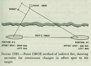
Since the motion of the firing ship continuously changes the values of the offsets from the point of aim, frequent changes in these offset spots must be made to ensure hitting the target. This problem is illustrated in figure 22B5. One way to determine correct range and deflection spots continuously is to use a small transparent overlay on which are inscribed 100-yard squares drawn to the same scale as the chart. With the center of the gridded overlay on Point OBOE, and the grid lines oriented to the direction of the line of sight from the ship, range and deflection spots to hit the designated target may be read directly from the grid overlay.
4. Indirect fire: functions of CIC. The primary function of CIC in naval gunfire support is to keep an exact check on the ship’s position and from this to determine ranges and bearings to targets designated for indirect fire. It can be readily appreciated that the accuracy of fire, when using the method previously described, depends primarily on the skill of the CIC team. CIC also keeps a record of own troop front-line positions, target locations, and other information pertinent to the support of the troops ashore. It acts as the clearing house for information to and from the shore fire control party and air observer, with whom it has direct voice radio communication. Thus in naval gunfire support, CIC keeps the ship’s commanding officer, gun control, and plot advised regarding the requirements for support; furnishes the information necessary to provide the support; and gives the shore fire control party such information as may be necessary or useful. In addition to target range and bearing, CIC must determine, from contour lines of the bombardment chart, the elevation of the target above sea level and send this to the plotting room so that range error resulting from this elevation may be corrected in the computer.
On heavy ships (battleships and cruisers) the above functions of CIC are often performed in a section of the plotting room. This leaves the ship’s CIC free for the other vital duties it must perform.
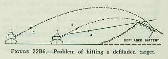
5. Special fire control problems of naval gunfire support. Targets which are located on the far slope of a hill or similar terrain feature lying between the firing ship and target present a particularly difficult problem to the flat trajectory of naval gunfire. This problem (defilade fire) requires obtaining an angle of fall which will clear the crest of the hill and be steep enough to hit the target beyond. When this situation occurs, the angle of fall is chosen which is greater than the angle of the reverse slope. Two solutions are then available. The ship may either increase the range to obtain the angle of fall selected, or it may use reduced-velocity charges at the shorter range to obtain this selected angle of fall.
In figure 22B6, which illustrates this problem and its solutions, A is the trajectory produced by standard service charges and is too flat; B is the trajectory which can be obtained by using reduced-velocity charges; C is the trajectory which can be obtained with standard service charges by increasing the range. In the event it is necessary to fire over friendly troops occupying an elevated position between the firing ship and the target, it is necessary to determine the elevation of the target, the elevation of the troop position, and the difference between the two. Call this difference y, and the horizontal distance between the troop position and the target x. By referring to trajectory curves, you can determine the range at which the abscissa x yards from the point of impact is safely greater than the difference in elevation y. This is the limiting range outside of which it is safe to fire.
22B7. Spotting by target grid system
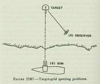
Spotting, as it applies to naval gunfire in general, was discussed in chapter 18. All the general principles contained therein apply in shore bombardment spotting, but additional considerations apply also, especially when spots are to be made by a shore fire control party.
A spotter ashore must be advantageously located to observe the fall of shot. In most cases this requires that he be as close as possible to the enemy positions which will have to be taken under fire; this presents him with a very serious front-line problem of survival.
Spots made by an observer aboard the firing ship are naturally oriented to the line between the firing ship and target (called the gun-target line). Spots made from aircraft can be oriented readily to the gun-target line, since both the gun and the target are normally within the aircraft observer’s field of vision. But spotters ashore are frequently unable to see the firing ship and, so long as they were required to make their reports in relation to the gun-target line, this seriously limited the value of the information sent by the spotter to the ship.
To simplify this problem for the spotter, the Army Artillery School at Fort Sill developed the target-grid system for use in spotting the fall of shot on land. As a result of trials in joint exercises, the target-grid system has been incorporated into the Standard Spotting and General Shore Bombardment Procedure for use within the naval service.
The objective of this system is to permit the observer to spot the fall of shot just as he sees it along his own line of sight to the target, called the observer-target line, irrespective of the position of the firing ship and of the gun-target line. The procedure is briefly outlined as follows (refer to fig. 22B7).
1. The observer, in his call for fire, must give the azimuth from himself to the target; direction OT in the illustration.
2. The observer makes all his observations and corrections with respect to the observer-target line (OT).
3. The CIC or plotting room crew converts the corrections of the observer to corrections with respect to the gun-target line (GT).
4. The plotting room crew introduces into the rangekeeper (computer) the spots corrected to the gun-target line.
22B8. Grid spot converter

The grid spot converter is a device used to convert graphically the corrections given by the spotter from the OT line (spotter’s line of sight) to the GT line (ship’s line of fire). It consists of two superimposed concentric circles with horizontal and vertical lines etched on them, forming squares, each dimension representing 100 yards. The lower circle is etched in black on the face of the converter; it is stationary. Its circumference is graduated counterclockwise in degrees from 0° to 360°, with 0° at the top. The 0-180 diameter of this circle is a black arrow, with the arrowhead at zero degrees. The upper circle is etched in red on a movable, transparent plastic disc; this disc is mounted concentrically over the lower circle, so that it is free to rotate about its center. The circumference of the upper disc is graduated counterclockwise in mils from 0 to 6,400, with 0 mils at the top. The 0-3,200 diameter of this disc is a red arrow, with the arrowhead at zero mils. The lower disc is the own-ship disc, and the black arrow represents the GT line. The upper, movable disc is the observer disc, and the red arrow represents the OT line.
The grid spot converter is used as follows (see fig. 22B8):
1. The converter operator obtains the true azimuth of the GT line in degrees by reading the true target bearing on the own-ship dial group of the computer. He makes a mark with a grease pencil at this azimuth on the lower (black) disc. He then obtains the azimuth of the OT line from the observer (spotter) via CIC. He makes another mark at this azimuth on the upper (red) disc.
2. The operator then rotates the upper disc until the two pencil marks are opposite each other. In the figure, GT is 1,400 and OT is 1,500 mils. See pencil marks. The red and black arrows now indicate the angular relationship of the observer’s line of sight and the ship’s line of fire.
3. When a spot is received from the spotter, the operator starts at the center of the upper disc, which represents the burst, and plots “Right 200; add 500” along the lines perpendicular to and parallel to the red arrow. The point plotted then represents the target, which is marked with grease pencil. He now goes back to the burst (center) and counts off the squares to the target, on the lower disc, perpendicular to and parallel to the black arrow. This gives a spot of “Left 300, add 450”, which is relative to the ship’s line of fire. This is the spot which is applied to the computer (Left 300 is in yards, and must be converted to mils before it can be applied).