
Chapter 20 of Naval Ordnance and Gunnery, Volume 2 — Fire Control covers the main-battery fire control systems of battleships and cruisers as designed primarily for the surface fire control problem. The chapter uses the Baltimore and Oregon City class heavy cruisers as the type example, tracing the complete system from aloft gun directors through the plotting room to turret fire control equipment and main-battery radar.
A. General
20A1. Introduction
Main-battery fire control systems in battleships and cruisers, other than antiaircraft cruisers, are designed primarily to handle the surface fire control problem, discussed in chapter 19. Although the present trend is toward development of automatic major-caliber guns capable of handling either the surface or the air problem, the great majority of main-battery systems now installed have very limited secondary provisions for antiaircraft fire.
The control of turret batteries against aircraft is made possible on most ships by interlocking arrangements between the main battery and the dual-purpose systems. The variety and complexity of these cross-connections preclude their analysis in this text.
20A2. System elements
The principal elements of a main-battery fire control system are located in four types of stations aboard ship. These stations are:
1. The control stations.
2. The aloft gun directors.
3. The plotting rooms.
4. The turrets.
20A3. Central systems
The Gunnery Officer has a station of his own, accessible to the Commanding Officer, and better protected than the gun directors. In battleships and some cruisers, this station is protected by heavy armor and is known as the fire control tower. In many ships there is a similar station aft from which all or part of the main battery may be controlled.
Either or both of these stations may be equipped to take over many of the functions of both the director and the plotting room in case of casualty, or they may serve merely as supervising and observing stations. In either case periscopes and indicating equipment are installed. In addition, there may be some of the following equipment:
1. Auxiliary gun directors, such as the Mark 40 or Mark 55.
2. Auxiliary computers (Mark 3 or Mark 6).
3. Control consoles, as well as indicators, for the Radar Equipment Mark 13.
4. An independent radar equipment (Mark 27).
5. A stable element (Mark 6) for use with the auxiliary computer.
20A4. Aloft gun directors
All battleships and cruisers have two primary gun directors, each equipped with both a radar and a rangefinder. The forward primary director is also the ship's primary spotting station and is usually under the direct personal command of the ship's leading spotter.
Cruisers of the Baltimore, Oregon City, Cleveland, Fargo, and Brooklyn classes are equipped with Gun Directors Mark 34 of various Mods. This director mounts a Rangefinder Mark 45. New heavy cruisers of the Salem class have Gun Directors Mark 54, which differ from the Mark 34 in having more complete provisions for control of the main battery against aircraft. The accompanying rangefinder is the Mark 66.
Battleships of the North Carolina, South Dakota, and Iowa classes and large cruisers of the Alaska class mount Gun Directors Mark 38, equipped with Rangefinders Mark 48. This director differs from the Mark 34 principally in that it does not provide a stand-by source of gun orders as does the Mark 34.
Radar Equipment Mark 13 is used with all directors mentioned, although some of the older ships still have the earlier Radar Equipment Mark 8. Some of the subassemblies of the radar are not physically located in the director.
20A5. Plotting rooms
Main-battery plotting rooms, located below the waterline and inside the armor belt, characteristically contain:
1. Rangekeepers, including associated graphic plotters. Various modifications of the Rangekeeper Mark 8, differing from each other chiefly in the ballistic cams, are built for use with the following guns: 16"/50 caliber, 16"/45 caliber, 12"/50 caliber, 8"/55 caliber (both types), and 6"/47 caliber.
2. Stable-vertical gun directors. South Dakota class battleships are equipped with the Mark 43, while all the other ships under discussion use the Mark 41.
3. Some units of the radar equipment.
4. A fire-control switchboard and an associated battle-telephone switchboard.
5. Various indicators.
Cruisers, except for the Salem, and Worcester classes, have one main-battery plotting room, containing only one rangekeeper and stable vertical. In case of casualty or divided fire, auxiliary equipment and procedures must be used. Battleships and the Salem and Worcester class cruisers have duplicate rangekeepers and stable verticals, located in some ships in the same compartment, in others in separate compartments.
20A6. Turrets
As mentioned in chapters 7 and 10, some of the ship's fire control equipment is located in the turrets. Except for the latest types of turrets, equipped with radars instead of rangefinders, there is little difference between classes of ships in this respect.
B. A Typical System
20B1. Introduction
In this section, the system installed on the Baltimore and Oregon City classes of heavy cruisers will be described. This system does not vary in principle from other main-battery systems. The discussion will include brief descriptions of the stations and instruments comprising the system, illustrations, and explanations of the connections between them, and details of several ways in which the system is used to track a target and to position and fire the turret guns. It is concerned primarily with the functioning of the various pieces of equipment as parts of an integrated system, and the part which the officers and men of the ship play in operating this system.
20B2. General features of the system
The main battery consists of nine 8"/55 caliber guns mounted in three triple gun turrets. Turrets 1 and 2 are forward and turret 3 aft. All turrets can be trained through 300° (150° on either side of the centerline). The guns can be elevated 41 degrees above and depressed 5° below the deck plane. Each gun is independently controlled in elevation.
The fire control system is designed to aim and fire the guns at moving surface targets within the range of about 30,000 yards (approximately 15 miles).
Preliminary information concerning targets is transferred to the fire control party through the target-designation system, which has associated equipments located at various points on the ship, such as search-radar consoles and lookout stations. This information is combined with other estimated or measured quantities, whereby the system computes sight angle and sight deflection. The system also measures level and cross-level, and from all these data computes gun orders.
20B3. Principal system components
The system of fire control used on these ships is known informally as the Gun Director Mark 34 system.
Gun directors. The two primary directors are located above the main-battery fire control stations. Their basic function is to determine the LOS to the target by pointing the telescope or the radar antenna toward it. Range is measured by the radar or the rangefinder in the director and, together with target bearing, serves to locate the target's present position. Under certain conditions, such as divided fire or casualty operation, the directors may assume some of the functions of the stable vertical and rangekeeper by measuring level and crosslevel and computing gun orders, using data furnished by auxiliary computing equipment. Corrections are made at the director for both horizontal and vertical parallax, based on the distance to the ship's reference point and the mean height of the gun trunnions, respectively.
Plotting room. The plotting room (Plot) contains a stable vertical, a rangekeeper, some units of the radar equipment, and a main-battery switchboard.
The auxiliary main-battery switchboard is located in the after gyro room. It is connected to the system in such a way that it can substitute for the main-battery switchboard in Plot if the latter becomes inoperative. By means of this switchboard any director can be connected to any turret or group of turrets without using main-battery plotting-room facilities.
Turrets. Within the turret are three elevation receiver-regulators and a train receiver-regulator. These instruments control the hydraulic gear by which the turret is trained and the guns elevated in accordance with gun orders. These orders may originate at the plotting-room rangekeeper, at either of the aloft directors, or locally at the pointer's and trainer's handwheels.
The turret also contains one turret-train indicator and transmitter, and three gun-elevation indicators. These are follow-the-pointer units by means of which gun orders from the plotting room or elsewhere may be received electrically to be matched by handwheel operation. The train transmitter sends turret train for information purposes only to turret train indicators in various stations.
Also provided is a sight setter's indicator, by means of which the sight setter sets the sights and supplies certain correction quantities for train and elevation instruments. In order to be independent of the rest of the system for local fire control, if necessary, the turret is also equipped with pointer's and trainer's gun-sight telescopes, a rangefinder, and an auxiliary computer.
Synchro transmission. The synchro transmission system transmits data and orders between the elements of the system. The single lines each represent a group of conductors. Selector switches at each fire control station and at each turret are provided to connect the turrets with either the main-battery or auxiliary main-battery switchboards. At the switchboards provisions are made for interconnecting the directors and turrets.
The firing circuits permit the guns to be fired by firing keys at various stations — in the directors, the plotting room, or the turrets. These keys are used for electric firing by hand keys. In automatic key firing, the guns are fired when contacts in the stable vertical are closed at a selected value of level or crosslevel. Ready lights and salvo signals are provided at all stations. Time-of-flight signals are provided at the directors and fire control stations, and in the plotting room.
20B4. Capabilities of the system
The fire control system may be operated in several different ways. This flexibility permits fire to be maintained in the event of casualty to parts of the system, and provides for firing at two or more targets at the same time.
Types of fire control. The different types of fire control are distinguished by the source and transmission route of the gun orders. The types of control are primary, secondary, auxiliary, local, and antiaircraft. These types, except the last named, are shown in figure 20B1.

In primary fire control, the target is tracked by one of the directors; gun orders are computed by the rangekeeper in Plot and transmitted to the turrets via the main-battery switchboard.
In secondary fire control, the target is tracked and gun orders are computed by one of the directors, with data supplied from the rangekeeper in Plot or from auxiliary equipment. Gun orders pass to the turrets via the main-battery switchboard.
Auxiliary fire control is similar to secondary fire control, except that the auxiliary switchboard is substituted for the main-battery switchboard in Plot.
In local fire control each turret utilizes local instruments and sights to solve the problem and aim the guns, and operates as a self-contained unit.
For antiaircraft firing, provision is made to connect the main-battery system to receive gun orders from the secondary (dual-purpose) battery system, so that the 8-inch guns may be used for antiaircraft fire. The long range of these guns makes them useful for firing on enemy planes which are grouping for attack beyond the range of the 5-inch guns. Differences in ballistics between the secondary-battery and the main-battery guns make necessary the application of corrective spots to the gun orders computed in the secondary-battery computer. This limits the effectiveness of this system against aircraft.
Methods of gun laying. Figure 20B1 is a schematic diagram showing the available types of fire control and methods of gun laying and of turret drive.
The different methods of operation by which the guns may be positioned are: automatic gun laying, in which the receiver-regulator controls the A-end; indicator gun laying, where an indicator is used to guide the handwheel operator; or local gun laying, where the gunsight telescopes are so used.
Methods of drive. The methods by which the handwheels control the driving of an element are local power drive and hand drive. In local power drive the handwheels are geared to the receiver regulator, which in turn controls the A-end of the hydraulic gear. In hand drive the handwheels are geared to the A-end and thus control the hydraulic drive directly. Both of these methods of drive use an electric motor to supply power to the hydraulic gear for moving the element; the handwheels govern only the volume of fluid that is pumped by the A-end. In manual drive the electric motor is inoperative, so the A-end is driven by man-power applied to an emergency hand crank. The operator's handwheels (pointer or trainer) function as in hand drive.
In primary fire control, secondary fire control, and auxiliary fire control, either automatic or indicator gun laying may be employed. In local fire control, local gun laying must be employed. In both indicator and local gun laying, either local power or hand drive may be used, but in automatic gun laying these methods are not applicable.
Means of firing. Gun firing may be either by local key or by master key or by percussion; but percussion is used only when electric firing fails. Remote master keys at various stations in the ship may be used. In primary fire control, selected level or selected cross-level automatic key firing may be done automatically by the firing mechanism in the stable vertical. This method is not available in other methods of fire control.
C. Gun Directors
20C1. General
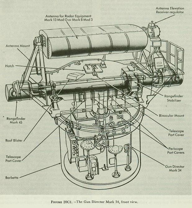
Each cruiser is equipped with two Gun Directors Mark 34 — No. 1 forward and No. 2 aft, mounted near the main-battery fire control stations. The director is enclosed in a shield which supports the rangefinder and radar antenna as shown in figure 20C1.
The directors may be used to measure the target coordinates (bearing, elevation, and range) in various manners, which must be defined.
Aiming is the process of establishing target position in bearing and elevation. Aim is classified as to type by the instrument employed: i.e., radar aim indicates the determination of bearing and elevation by radar; optical aim, by telescope. If, in association with determination of bearing by observation, elevation is determined by stabilizing instruments rather than by observation, the procedure is known as partial radar (or optical) aim. When neither bearing nor elevation is established by observation, but both by calculation of data otherwise introduced, the process is designated as generated aim.
Ranging is the process of establishing target distance from the firing ship. Like aiming, it is classified by means as radar ranging, optical (rangefinder) ranging, or generated ranging.
Both aiming and ranging may be either continuous or intermittent. Intermittent aim is directly associated with intermittent stabilization, and is therefore discussed in connection with the stable vertical in article 20E2. Intermittent ranging is employed when the means of ranging is by rangefinder; it is rarely used with radar ranging.
Continuous aim and ranging may be classified as to method as automatic, aided, or manual. Manual aim and ranging signify the positioning of the instrument used by the operator by hand in accordance with his observations. Aided operation means the positioning of the instrument in accordance with signals received from the rangekeeper, corrected as necessary by the operator as he observes the target (optically or by radar). Automatic ranging and aiming are not applicable to the system under discussion.
Each Gun Director Mark 34 is equipped to measure the three target coordinates, optically or with its associated radar equipment, and to transmit the values thereof (bearing and elevation after correction for parallax) to the rangekeeper. In addition, the director is equipped to take over some of the functions of the rangekeeper and stable vertical. It may be used to measure crosslevel optically. Under secondary fire control and auxiliary fire control procedures, and when supplied with sight angle and sight deflection from the auxiliary computer, the director can correct these quantities for trunnion tilt, combine them with level (director elevation) and director train respectively, and transmit the sums as gun elevation order and gun train order to the turrets via the main or auxiliary switchboards. In addition to these functions as instruments, the directors serve as lookout stations from which targets can be located and the fall of shot spotted.
20C2. Description
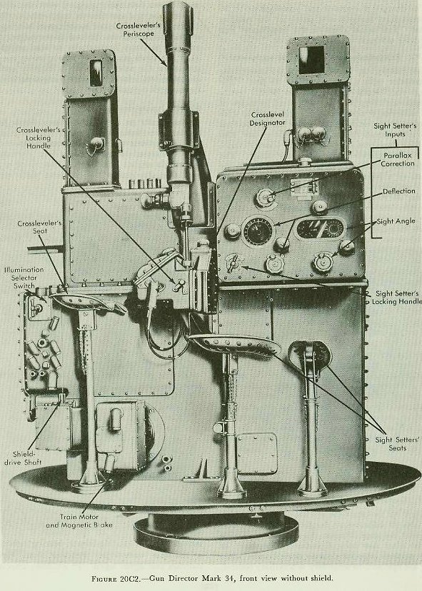
The director proper provides stations for a crew of eight men within the shield. At the rear of the director are stations for the trainer, pointer, spotter, and radioman. The rangereader's seat is attached to the shield. At the front of the director (figure 20C2) are stations for the crossleveler and two sight setters. Each station provides a seat and the handwheels, switches, dials, optics, and other apparatus used by the operator. The spotter is provided with binoculars, which are mounted on the roof of the director shield.
The instruments and assemblies within the director include the following:
1. The trainer's units.
2. The pointer's units.
3. The crossleveler's unit.
4. The sight setter's unit.
5. The computing units.
6. The director drive system.
20C3. Trainer's units
The trainer's units are those which implement or facilitate tracking the target in bearing. They may transmit director train, train designation, and gun train order, and receive train designation and ownship course.
The trainer tracks a visible target by turning his handwheels to bisect the target image with his telescope vertical crossline, thus training the director and determining director train. He may also use an auxiliary radar indicator for tracking the target in blind firing. As the director is trained, the radar antenna mounted on the shield turns with it. When the target echo on the radar scope is bisected by the center bearing line, the director is trained on the target, and the correct value of director train is determined. Director train is corrected by the horizontal parallax mechanism which receives a parallax range input from the sight setter's unit. In primary control, corrected director train is transmitted by two sets of synchro generators; one set normally transmits observed director train to the rangekeeper, while the other set transmits train designation to other stations for information. In secondary and auxiliary control, deck deflection (that is, sight deflection corrected for trunnion tilt), received from the director computer unit, is added to corrected director train, and the result is transmitted by the observed-director-train synchros as gun train order.
20C4. Pointer's units
The pointer's units measure director elevation (which may be used as a substitute for level) corrected for vertical parallax. In one form of primary fire control, the director may substitute for the stable vertical in Plot, at which time the movement of the pointer's handwheels operates synchro generators which transmit director elevation to the rangekeeper. In another, it transmits director elevation to the stable vertical in Plot for positioning the automatic firing contacts for automatic key firing, with selected values of level. In secondary and auxiliary fire control the pointer transmits level mechanically to the director computer units, which position the pointer's unit synchros to transmit gun elevation order to the turrets via the switchboard. Follow-the-pointer dials provide level indication from the stable vertical in Plot or from an auxiliary stable element in the after fire control station, when the pointer is unable to keep his telescope crossline on the target or horizon. The pointer's handwheels also keep the trainer's telescope on the target in elevation.
20C5. Crossleveler's unit
The crossleveler's equipment is used only in secondary or auxiliary control. It consists of a periscope and a designator. The periscope has a divided field in which the horizon at two opposite points of the compass is visible. By bringing the images of the two parts of the horizon into line, the crosslevel is measured. The designator is a 36-speed follow-the-pointer dial which indicates crosslevel as received from the stable vertical, or the stable element in the after fire control station. When the pointers are matched, the crossleveler mechanically transmits this value of crosslevel to the computing units in the director, for the computation of trunnion-tilt correction in the formulation of gun orders. When crosslevel is measured by use of the periscope, it is also transmitted mechanically to the director computing units.
20C6. Sight setter's units
There are two sight setter's units, one for sight angle and one for sight deflection. The sight-angle unit consists of two follow-the-pointer dial groups, while the sight-deflection unit consists of a single follow-the-pointer dial group. Both units are operated in secondary and auxiliary control, receiving sight angle and sight deflection from the auxiliary computer in the fire control station, or from the rangekeeper, and relaying it to the director computing instruments. In primary control only sight angle is used. Sight angle is received from the rangekeeper, converted to parallax range, and used in computing parallax corrections for addition to observed director train and level.
20C7. Computing units
Mounted in the lower part of the director frame are two computing instruments, the trunnion-tilt corrector and the director-elevation corrector. These instruments are employed only in secondary and auxiliary fire control for the computation of gun train and gun elevation orders, using the following inputs: director train, level, crosslevel, sight angle, and sight deflection.
In primary fire control, the computing instruments are locked in their zero positions, so as not to interfere with the transmission of director train and level to the plotting room.
20C8. Director drive system
The director can be trained by three methods — automatic power, local power, and manual.
In the first method, automatic power drive, the director is trained automatically in response to an electric signal from the rangekeeper in Plot, which controls the amplidyne follow-up system.
This signal called —

— is the computed change in bearing required to keep the director continuously on the target. If, in this control, the trainer's crosslines tend to drift off the target, he turns his handwheels to bring the director back on target and signals Plot that a revision of estimated target quantities in the rangekeeper set-up is needed.
In local power drive the amplidyne follow-up system may be controlled by the trainer's handwheels; or the trainer's or spotter's slewing controls may be operated to rotate the director rapidly through large angles of train.
In the two drive methods where power is employed, local and automatic, an amplidyne follow-up system is used.
In manual drive the trainer's handwheels are connected through a clutch to the training worm, and the director and shield are rotated solely by the power applied by the trainer to the trainer's handwheels.
20C9. Shield
The director is enclosed and protected partly by the stationary barbette and partly by the rotating shield. The shield supports the rangefinder and the radar antenna, which turn with it.
20C10. Rangefinder and rangefinder equipment
The Rangefinder Mark 45 Mod 0 is a stereoscopic rangefinder with a base length of 18 feet. The range scale reads from 1,500 to 50,000 yards. Rangefinder range may be transmitted by means of the radar-range remote-control unit used in conjunction with the range indicator in this station. Two men operate the rangefinder — the spotter, who sights on the target and positions the wander marks, and the rangereader, who reads the range. The rangefinder is stabilized in level either manually, by means of a hand lever, or automatically. Automatic stabilization is accomplished by either of two devices: the rangefinder stabilizer or the rangefinder elevation receiver-regulator (whichever is installed). The rangefinder stabilizer is a self-contained device which includes a gyroscope and an electric-hydraulic follow-up system connected to the rangefinder through a linkage system. The elevation receiver-regulator follows a level signal received from the stable vertical in Plot (or from the auxiliary stable element), and thus stabilizes the rangefinder.
20C11. Radar equipment
Most of the radar equipment associated with the forward director is located in the plotting room; that for the after director is in the after fire control station. For either type of radar equipment an antenna mounted on top of the director shield is supported by the radar-antenna mount, which automatically stabilizes the antenna in level by means of a receiver-regulator. Level signals to this unit are relayed from the plotting-room stable vertical or the auxiliary stable element by the antenna-elevation corrector inside the shield. The operator turns a hand crank on the corrector to set the antenna at the desired elevation, after which it is held automatically in that position, regardless of roll or pitch. The radar antenna transmits a directed radar beam into space parallel with the director line of sight, and also receives target echoes. When the target echo is bisected by the center bearing line of the indicators, the director is on target. The antenna oscillates horizontally to scan an arc of 11.5°, ten times per second. The operator can substitute for the service antenna a dummy antenna and echo box, which are used for checking the performance of the radar.
20C12. Inputs and outputs
The inputs to the Gun Director Mark 34 in primary fire control are:
1. Increments of generated director train.
2. Generated director train.
3. Sight angle.
4. Own-ship course.
5. Level.
6. Train designation.
7. Observed range.
Outputs of the director in primary fire control are:
1. Corrected director train (corrected for horizontal parallax).
2. Director elevation (not always used).
3. Range.
4. Train designation.
The inputs to the director in secondary or auxiliary fire control are:
1. Sight angle.
2. Sight deflection.
3. Own-ship course.
4. Level (after director only).
5. Crosslevel (after director only).
6. Train designation.
Outputs of the director in secondary or auxiliary fire control are:
1. Gun train order.
2. Gun elevation order.
3. Corrected director train.
4. Range.
5. Train designation (secondary fire control only).
D. Fire Control Stations
20D1. General
There are two main-battery fire control stations — one located adjacent to the forward director and one near the after director. Figure 20D1 is a view of the after fire control station. Equipment in these stations supplies data to the directors when they are operated in secondary or auxiliary control, which makes them independent of the plotting-room equipment. Each station contains: an Auxiliary Computer Mark 3, which supplies sight angle and sight deflection to the directors; periscope mounts, used in locating targets; bearing indicators; multiple turret-train indicator, and various switches and signal lights. In addition, associated with the after fire control station is a Stable Element Mark 6, which supplies level and crosslevel to the after director for blind firing in secondary control or auxiliary control, and the radar control equipment associated with the after main-battery radar installation.

20D2. Computer Mark 3
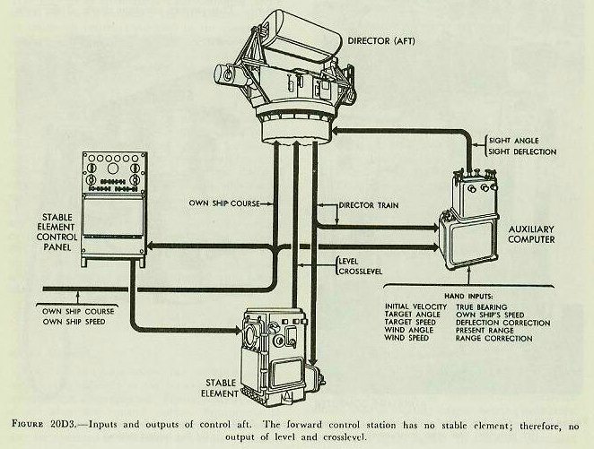
One computer, such as that shown in figure 20D1, is located in each fire control station. The computer is an auxiliary instrument for use in secondary or auxiliary control, or when the rangekeeper in the plotting room is inoperative. It is smaller and simpler than the Rangekeeper Mark 8. The predictions are less accurate than are those of the rangekeeper, and therefore more corrections may have to be introduced by hand. Unlike the rangekeeper which produces gun orders, the auxiliary computer produces only sight angle and sight deflection.
The auxiliary computer solves the fire control problem (for sight angle and sight deflection) for all movements of target and ship, and for wind across the line of sight. Director train is relayed to the computer by a target-bearing receiver.
Inputs and outputs of the auxiliary computer are shown in figure 20D3.
In secondary control, sight angle and deflection are routed to the director through the main-battery switchboard, from which they are also transmitted to the turrets. In auxiliary control, the values are transmitted directly to the director, and must be telephoned to the turrets.
The computer in the after control station, by means of a range transmitter mounted on the computer, transmits generated change of range to the radar equipment in the same station. This quantity is used in the radar equipment in such a manner that aided range tracking is provided for the radar operator in both secondary and auxiliary control. This permits constant check of the computer solution with observed optical range and radar scope indications.
20D3. Periscope mount
Each fire control station contains one or two periscope mounts. Each mount, as shown in figure 20D2, supports a rotatable periscope, whose relative bearing angle is shown on an attached bearing indicator. The instrument is used for locating targets, and information thus obtained is telephoned to other stations.

20D4. Bearing indicator
The fire control stations each contain two bearing indicators, which are also shown in figure 20D1. The bearing indicator indicates three quantities:
1. Relative target bearing, obtained by reading the fixed-dial graduations opposite the index on the ring dial.
2. True target bearing obtained by reading the inner dial graduations opposite the index on the ring dial.
3. Own-ship course, obtained by reading the inner dial against a fixed index.
Each bearing indicator receives director train from one of the aloft directors and own-ship course from the ship's gyro compass.
20D5. Multiple turret train indicator
A multiple turret train indicator (MTTI) is shown in figure 20D1 mounted on the forward bulkhead of the after fire control station. An identical instrument is provided in the forward fire control station. These instruments indicate modified turret train response for each of the three turrets on one set of dials, and show the difference between modified train response and gun train order on another set of dials. Modified train response is turret train corrected for horizontal parallax. Thus, the dials indicate whether or not the turrets are trained in accordance with gun train orders.
E. Main-Battery Plotting Room
20E1. Location
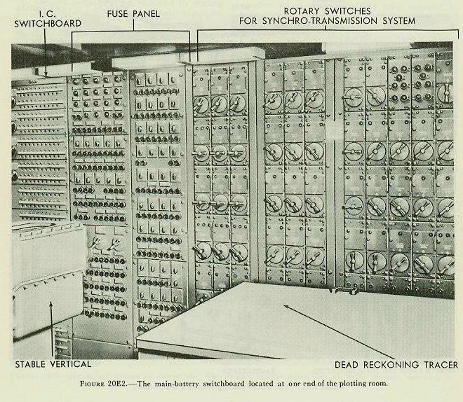
The main-battery plotting room is located opposite the secondary-battery plotting room. Its location below the waterline and beneath the armored deck is to ensure maximum protection from enemy action. The arrangement and location of the equipment differ somewhat among ships; figure 20E1 shows a typical installation, while figure 20E2 shows the main-battery switchboard.

The principal items of equipment in the plotting room are: the Gun Director Mark 41 (stable vertical), with its control panel; the Rangekeeper Mark 8, the radar equipment associated with the forward director, and the main-battery fire control switchboard. In addition to these principal items, there are a gun train order relay transmitter, bearing indicators, range indicators, multiple turret train indicators, a graphic plotter on the rangekeeper, director train indicators, telephone equipment, and various switches and signal lights. Some ships are provided with a dead-reckoning tracer in main-battery Plot.
The plotting room is the primary source of gun train and gun elevation orders. To it, in primary fire control, are brought the data measured and estimated at the directors; from it are transmitted the data used to position the gun.
20E2. Gun Director Mark 41 Mod 0 (stable vertical)
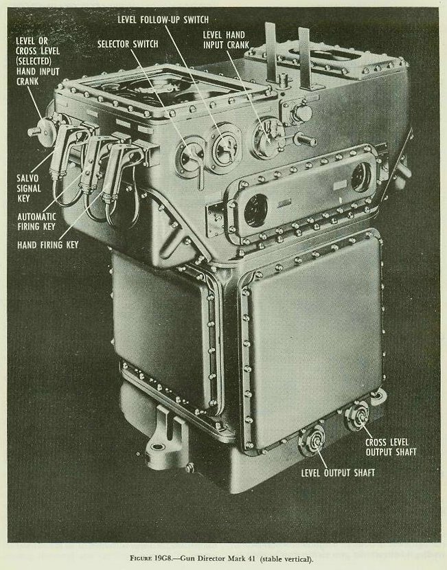
The general appearance of the stable vertical is as shown in figure 19G8.
In the previous chapter the stable vertical was discussed only as an instrument which designates and maintains the true vertical and its associated horizontal plane, and by so doing, continuously measures level and crosslevel. Another function of the stable vertical is its use as a remote firing station. The utilization of it as such is associated with methods of aiming designated as continuous and intermittent. Intermittent aim is that method of aim in which target position is continuously measured in one coordinate and periodically measured in the other; thus it may be subdivided into selected elevation, in which bearing is the element continuously measured, and selected train, in which elevation is the quantity continuously measured.
If continuous aim is in use, it is possible to fire the guns at any point in the motion of the ship in roll and pitch. Thus this method may be called, as it is on the nameplates of the stable vertical, “continuous fire,” although this term must not be confused with the use of the same term to indicate a method of gun firing as defined in article 18A2.
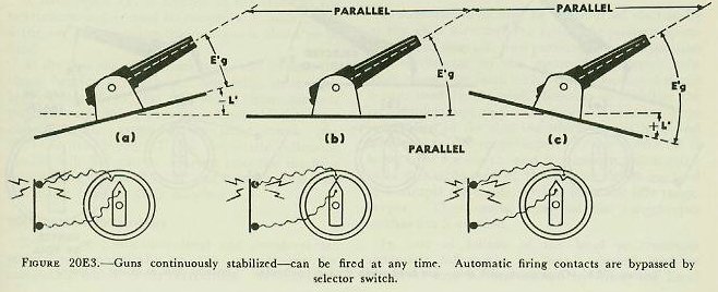
Continuous aim is used under normal sea conditions. The stable-vertical selector switch is set to CONTINUOUS FIRE, and both level and crosslevel as generated in the stable vertical are transmitted continuously to the rangekeeper. This results in gun train order and gun elevation order being continuously corrected for inclination of the deck. The guns may be fired by closing a hand firing key at the front of the instrument. Note that the gun maintains its position in space, while E′g continuously changes as L′ changes. Figure 20E3 illustrates continuous aim. (At times it is desirable to have the director pointer, rather than the stable-vertical operator, do the firing. This may be accomplished by keeping the stable-vertical key closed, so that the only break in the current is at the firing pointer's key. When his key is closed, the circuit is complete.)
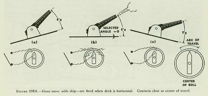

Intermittent aim is used when sea conditions make it difficult for the guns to stay on target. In this method of aim the guns are not continuously stabilized but move with the ship, as shown in figures 20E4 and 20E5. It thus becomes necessary that the guns be fired only at such moments as aim is correct. To accomplish this, master-key fire from the stable vertical is used, preferably utilizing the automatic contact makers provided for this purpose.
The stable vertical is a device for indicating the true horizontal plane, and for measuring the values of level and crosslevel. It may be separately mounted or incorporated in a gun director.
Since at the stable vertical the quantities which are measured are level and crosslevel, the intermittent aiming methods must, from the point of view of the operator, be considered as selected level and selected crosslevel. Since selected crosslevel is less frequently used, only selected level is described in detail.
In selected-level operation the selector switch is set to LEVEL FIRE, and a fixed value of level angle is set into the stable vertical by hand (or electrically from the director in some cases). This value is usually selected so as to cause aim to be accurate and thus the guns to fire at about the middle of the ship's roll, and the same fixed value of selected level is transmitted from the stable vertical to the rangekeeper. It is apparent from figure 20E4 that since the angle between the deck and the gun (E′g) remains constant, there is one and only one position of the deck at which the aim is correct; that is, when the value of L′, measured in the stable vertical, exactly equals the selected value of level (L′j) being transmitted. In order to ensure that the guns will fire at this instant, a set of firing contacts closes the circuit automatically when the above condition exists.
Any value of selected level L′j may be chosen. Figure 20E4 shows the special case where L′j=0, and figure 20E5 is an example where L′j=5 degrees.
Selected-crosslevel operation is similar to selected-level, except that transmission of level remains continuous while transmission of crosslevel is fixed.
20E3. Operation


Figure 20E6 shows a top view of the stable-vertical face, with the various dials indicated. Figures 19G8 and 20E7 are side views, showing the arrangement of cranks, switches, and firing keys.
In the front right and left corners of the dial face are the generated level and crosslevel dials. These dials are driven by the L′ and Zh follow-up motors and continuously show values of L′ and Zh being generated.
In the center of the dial face is a small window indicating the setting of the stable-vertical selector switch, located on the right side of the instrument. This window reads CONTINUOUS, LEVEL, or CROSS-LEVEL, depending upon the method of operation selected.
The selected level or crosslevel dials at the front center of the dial face are set by the hand crank on the front side of the instrument. This dial group shows the value of either L′j or Zhj, depending upon the method of operation selected. Selected values of level and crosslevel may be received by these dials electrically from the director, if the hand input crank is disengaged.
The level and crosslevel automatic firing contact assemblies referred to in article 20E2 are located at the rear of the dial face. These contacts are used only in intermittent methods of aim. When continuous aim is being used, the automatic contacts are by-passed.
When the guns are fired by selected level (or crosslevel) procedure, the automatic firing key located adjacent to the hand key must be closed when the battery is ready to fire. The actual firing instant will then occur when the automatic contacts are made. The inner contact remains in the position shown in the figure; the outer contact is positioned in accordance with the generated level (or crosslevel) angle plus the additional selected level (or crosslevel) angle, so that it oscillates back and forth with respect to the inner contact as the generated angle changes. The firing circuit is completed momentarily when the outer contact sweeps past the inner one, thus firing the battery automatically when the selected and generated values are equal.
The stable vertical contains a firing mechanism consisting of contacts and a firing delay compensator, so arranged that the firing time is advanced to compensate for the ejection time of the projectile, thus ensuring that it leaves the gun at the selected value of level or crosslevel, as required.
These contacts may be connected, at the fire control switchboard, in series with the firing keys in the aloft director or at the stable vertical so that automatic selected level or crosslevel firing is possible from either of these stations. In addition to the above-mentioned automatic firing key, the stable vertical has a hand key which is normally used for continuous fire. In this type of fire, during which the guns are constantly stabilized, the hand firing key is part of the series firing circuit, and a selector switch shorts out the automatic firing contacts used in selected fire.
The hand firing key may also be used in selected fire, should the automatic firing mechanism become inoperative. The key is closed when the index marks of the firing contacts coincide.
A salvo-signal key is located at the front of the instrument and is used in conjunction with either firing key as a warning that a salvo is about to be fired.
At the rear top of the instrument can be seen the target bearing dial group. Normally, these dials are positioned by the B′r′ signal from the director through automatic follow-up action. Under these conditions the target-bearing hand crank (fig. 20E7) is disengaged. If the automatic follow-up should fail, B′r′ can be entered into the machine by engaging the hand crank and turning it to keep the target bearing dials matched.
20E4. Interrelationships
Selected or continuous level and crosslevel are transmitted electrically to the rangekeeper for computing trunnion-tilt corrections. Whether the transmissions are continuous or selected depends upon the aiming method of operation employed. In continuous aim, continuous values of both quantities are transmitted. In selected-level operation, a selected value of level and continuous values of crosslevel are transmitted. Continuous level and selected crosslevel are transmitted in selected crosslevel.
Simultaneously with the electrical transmissions, and regardless of whether intermittent or continuous aim is employed, continuous values of both quantities are transmitted mechanically to the rangekeeper for computing deck-tilt correction (j′B′r′). Were these additional continuous transmissions not made, deck-tilt correction would not be practicable in selected level or selected crosslevel.
Continuous level may be transmitted electrically to the aloft directors for follow-the-pointer operation by the director, thus permitting level operation in the director in the event the pointer's telescope cannot be used. This continuous-level signal is also used in the aloft directors to stabilize the rangefinders and radar antennae. A selector drive is installed in the shafting which carries level and crosslevel to the rangekeeper. When a director is being used for search, and is receiving stabilization from the stable vertical, the selector drives are used to uncouple the stable vertical from the idle rangekeeper. Thus undue wear on the rangekeeper mechanism is avoided.
In case of failure of the level or crosslevel automatic follow-ups, or both, selected level or crosslevel may be maintained by using the hand follow-ups, the galvanometers, and the hand firing key.
Dials are provided to indicate values of target bearing, measured level and crosslevel, selected values of level or crosslevel, and firing-delay compensation.
20E5. Stable-vertical control panel
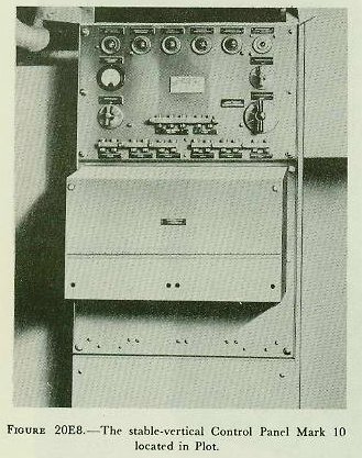

This panel is shown in figure 20E8. It contains the various switches, fuses, signal lights, and other apparatus necessary for the control of the stable vertical. The stable vertical panel also contains the switches operating the mercury cut-out valve which prevents malfunctioning of the gyro during high-rate maneuvers of own ship. These switches require synchro inputs of own-ship speed and course for their operation.
Inputs and outputs of the stable vertical and control panel are shown in figure 20E9.
20E6. Rangekeeper Mark 8
The rangekeeper includes most of the controlling, computing, and transmitting fire control mechanisms for the battery. The instrument is a combined rangekeeper, bearing keeper, predictor, deck-tilt corrector, trunnion-tilt corrector, and graphic plotter. Given the hand and automatic inputs listed below, the instrument will compute, indicate, and transmit electrically the information necessary to point the guns and set the sights continuously, and to train the directors and radar antennas continuously on the target. Outputs include the necessary corrections for drift, for wind, for variation in initial velocity, for relative movement of ship and target, for tilt of the gun trunnions from a horizontal plane (trunnion tilt) and for inclination of the director roller path from a horizontal plane (deck tilt). A time-of-flight signal mechanism, which electrically actuates local and distant buzzers indicating the fall of salvos, is included. The graphic plotter automatically plots ranges, sight deflection and time, and the magnitude and time of application of range and deflection corrections. The rangekeeper is equipped with synchro transmitters and receivers, which are used for all electrical inputs and outputs, except for those received by signal lights and those transmitted to lights or buzzers.
1. Inputs. Inputs are introduced manually by knobs, and automatically by mechanical and electrical transmission. Some inputs are used to set up the fire control problems, while others are concerned with the transmission of quantities and signals. Of these inputs, the following are used to set up the fire control problem:
Hand Inputs
a. Powder charge and projectile.
b. Initial velocity.
c. Target course.
d. Target speed.
e. Wind direction.
f. Wind speed.
g. Ship course.
h. Ship speed.
i. Present range.
j. Generated target bearing.
k. Observed director train.
l. Deflection correction (spot).
m. Range correction (spot).
n. Time.
o. Level.
p. Crosslevel.
Some of the hand inputs listed above are for emergency use when certain automatic inputs or motors in the instrument are inoperative. Items g, h, j, i, k, n, o, and p are set in by hand only when the corresponding electrical input fails. Items bb and cc below are used only when the electrical follow-up of sight deflection or sight angle, respectively, is inoperative. In the event of failure of the time motor, item ee below is used to drive the mechanism normally driven by that motor.
Mechanical Inputs
q. Level (continuous).
r. Crosslevel (continuous).
Continuous values of level and crosslevel, items q and r, are transmitted mechanically from the stable vertical to the rangekeeper, where they are used to drive mechanisms in the deck-tilt computer.
Electrical (Synchro) Inputs
s. Ship course.
t. Ship speed.
u. Observed director train (automatic).
v. Observed director train (indicating).
w. Range.
x. Level.
y. Crosslevel.
Ship course, observed director train (automatic), level, crosslevel, and range are each received by a pair of synchro receivers equipped with a follow-up device. The latter drives different parts of the mechanism in accordance with the value of the quantity controlling it. Ship speed is similarly received by a single synchro receiver. Observed director train (indicating) is received by a pair of synchro receivers which drive indicating dials only. These dials are used for the introduction of observed director train by hand. Similar dials are driven by the level and crosslevel synchro receivers, in addition to their function of controlling follow-ups.
Additional inputs used only to transmit quantities or signals are:
Hand Inputs
aa. Selected train.
bb. Sight deflection.
cc. Sight angle.
dd. Range-scale shift.
ee. Manual power.
ff. Time of flight (setting of signal mechanism).
Electric (Other Than Synchro) Inputs
gg. Range-mark signal.
hh. Director-ready signal.
A director-ready signal, which indicates that the director is on the target in train, is received and indicated at the rangekeeper by two sets of signal lights. Range-mark signals received from the radar equipment actuate mechanisms in the graphic plotter which plot values of the radar range.
2. Outputs. Outputs transmitted electrically are as follows:
a. Gun train order (automatic).
b. Gun train order (indicating).
c. Gun elevation order (automatic).
d. Gun elevation order (indicating).
e. Sight deflection.
f. Sight angle.
g. Increment of generated director train.
h. Generated director train.
i. Time-of-flight signal.
j. Rangekeeper signal to rangefinders.
k. Plot-ready signal.
l. Generated change of present range.
Outputs a to h inclusive are transmitted by synchro transmitters. Outputs i and j operate buzzers at distant stations, while k controls signal lamps at distant stations. Increments of generated director train are transmitted to the aloft controlling director, where it enables the director to be trained automatically. As an auxiliary method of control, generated director train can be substituted in the rangekeeper and stable vertical for observed director train, in case the target is obscured or the transmission from the exposed director is temporarily interrupted. Gun train order (automatic) and gun elevation order (automatic) are transmitted to the turrets for automatic gun laying. Gun train order (indicating), gun elevation order (indicating), sight deflection, and sight angle are transmitted to the respective indicating instruments in the turrets and at other stations. There are no mechanical outputs.
One of the important functions of the rangekeeper is the generation and transmission of increments of generated director train. The quantity, as initially computed in the rangekeeper, is based on electrical inputs of own-ship speed and course, and estimates of target speed and course set in by the operator. Own-ship quantities are accurately measured, but the target estimates may be in error. As the director is trained automatically in response to the generated signal, the director trainer observes the target by means of his telescope or radar indicator. If it is seen that the director tends to drift off the target, the trainer, by means of his handwheels, adds the motion necessary to keep it on. Remote control of such corrections is also possible; the radar operator in Plot is provided with a separate train transmitter with which he can correct director train in accordance with his radar scope indications. A constant comparison of generated and observed director train is presented to the rangekeeper operator on dials in the rangekeeper. With this information available, the rangekeeper operator needs only to be assured that the director is on the target before adjusting the target estimates. The on-target signal is given by the director trainer by means of a signal contact maker provided in one of his handwheels.
3. Generated director train. This quantity is an initial setting of director train plus the summation of increments of generated director train mentioned in the preceding paragraph. It is, therefore, the computed angle between the center line of own ship and the director line of sight measured in the plane of the deck.
Generated director train is transmitted to the train designator in the controlling director for follow-the-pointer operation by the director trainer. This use enables the director trainer to stay on the target in local power (or manual) operation, should the target become temporarily obscured. Lack of agreement between the generated and observed quantities is indicative of erroneous estimates of target movement used in the rangekeeper solution. It is emphasized that generated director train is not used to train the director in automatic operation.
4. Range. As originally designed, the rangekeeper computes generated present range and advance range, which may be read on counters on the face of the instrument. Generated present range is the sum of initial measured range between own ship and target, computed change of range in a given time interval due to relative movements of own ship and target, and any range corrections that may have been applied. As previously stated, advance range, used for sight-angle computation, is the sum of generated present range, computed range predictions, and ballistic corrections. Both quantities (generated present range and advance range) are employed solely in the rangekeeper; they are not transmitted outside the instrument.
Generated change of present range is transmitted to the radar control console in the plotting room, and observed range is entered into the rangekeeper solution automatically. If the rangekeeper solution is incorrect, the radar operator at the control console may superimpose corrections on the transmitted signals, thus causing rotation of a solution-indicator dial on the rangekeeper. The rangekeeper operator then corrects the set-up by modifying the inputs of target course and speed, in order that the radar equipment may track the target correctly. This method of ranging is known as aided ranging.
5. Corrections. The rangekeeper also computes trunnion-tilt and deck-tilt corrections, but does not transmit these quantities.
a. Trunnion-tilt correction. The computations made by the trunnion-tilt corrector are based upon measured values of level and crosslevel received from the stable vertical and computed values of sight angle and sight deflection. The computed corrections are applied in the rangekeeper to sight angle and sight deflection before addition of these quantities to level and director train respectively, to form gun elevation and gun train orders.
b. Deck-tilt correction. This quantity (jB′r′) is computed from observed director train received from the controlling director, and values of level and crosslevel received from the stable vertical. It is added to director train measured in the deck plane to obtain relative target bearing in the horizontal plane. This is needed, since the rangekeeper computes its solution in the horizontal. It can also be used to convert a value computed in the horizontal to one in the deck plane, as, for instance, increments of generated director train.
6. Graphic plotter. The graphic plotter is mounted on, and usually functions with, the rangekeeper. As originally designed, it records observed ranges from several remote stations, direction and time of application of deflection and range spots, values of generated and advance range computed by the rangekeeper, and the value of advance range existing when the time-of-flight button is pushed; and it plots continuously a trace of sight deflection computed in the rangekeeper.
After completion of current alterations, the graphic plotter will no longer receive and plot values of observed range from the several rangefinder stations, but instead will plot only values of observed range from the radar equipment. This will be entered into the rangekeeper solution automatically and plotted at the same time. Plotting of other quantities enumerated above will be carried out as heretofore.
Inputs and outputs of the rangekeeper are shown in figure 20E9 and figure 20F11.

20E7. Analysis of rangekeeper set-up
Since the rangekeeper solution of the problem is based on inputs, of which A, target angle, and S, target speed, are estimated, it is obvious that the values of E′g and B′gr, as solved by the rangekeeper, will be correct only if the estimated inputs are correct.
The analyzing feature of the rangekeeper provides the means for correcting the errors in setting target course and target speed. This operation is known as rate control and is defined as “the solution for correct target course and speed by causing the generated range and bearing rates to agree with the observed values.” Note that only one combination of target course and speed will cause both range and bearing rates to agree, and that this combination is the solution.
The amount and direction of change of target speed and target angle to effect such agreement varies for different conditions of target motion.
In the following discussion and in figures 20E10 through 20E13, it will be noted that no consideration is given to own-ship motion. This is justified because the accurately measured quantities representing own-ship motion are automatically and continuously being introduced to the rangekeeper computing mechanism. It can be assumed then that errors in RdBs and dR are caused entirely by errors in the target motion quantities, and therefore exist only in the computed target motion rates, Xt and Yt. In figures 20E10–13, the initial motion of the target and the initial values of Xt and Yt are indicated by the solid arrows. The changes in the initial values are indicated by the outline arrows and the letter j.


Effect of changing S. The effect that changing S has on the relative motion rates depends upon the direction of target motion relative to the line of sight, or target angle, A. If target motion is toward the right of the line of sight, an increase in S will make the deflection rate algebraically more positive. If target motion is toward the left, an increase in S will make the deflection rate more negative. When the estimated value of target angle indicates that the target's motion is away from own ship, an increase in S will cause the range rate to become positive; and with the target motion toward own ship, increasing S will make the range rate more negative.
When the direction of target motion is along the line of sight (A = 0° or 180°), changing S affects dR a corresponding amount without affecting RdBs. When the direction of target motion is at right angles to the line of sight (A = 90° or 270°), changing S affects RdBs a corresponding amount without affecting dR.
With the direction of target motion other than directly along or at right angles to the line of sight, changing S affects both dR and RdBs. When the direction of target motion is closer to being along the line of sight than at right angles to it, as in figure 20E10 (A between 135° and 225° or between 315° and 45°), changing S has a greater effect on dR than on RdBs. If the direction of target motion is closer to being at right angles to the line of sight than along the line of sight, as in figure 20E11 (A between 45° and 135° or between 225° and 315°), changing S has a greater effect on RdBs than on dR.
Effect of changing A. Changing A affects both dR and RdBs, the relative effect on each depending on the direction of target motion, or target angle, A. In the following examples, target speed, S, is assumed to be constant.
When the direction of target motion is closer to being along the line of sight than at right angles to it, as in figure 20E12 (A between 135° and 225° or between 315° and 45°), changing A has a greater effect on RdBs than on dR. But, if the direction of target motion is closer to being at right angles to the line of sight than along the line of sight, as in figure 20E13 (A between 45° and 135° or between 225° and 315°), changing A has a greater effect on dR than on RdBs.
From the diagrams shown in figures 20E10 through 20E13, it is also apparent that when A is changed so as to bring the direction of target motion toward the direction of the line of sight, the deflection rate due to target motion diminishes, while the range rate due to target motion increases. It should also be noted that changing A from any value toward the 0° value causes dR to become more negative; while a change in A toward 180° causes dR to change toward more positive values.
When A is changed so as to bring the direction of target motion at right angles to the direction of the line of sight, the deflection and range rates due to target motion increase and diminish respectively. Furthermore, changing A in the direction of its 90° value causes RdBs to become more positive, while a change toward 270° makes it become more negative.

Suppose that a situation exists as shown in figure 20E14. At position 1, own ship is on course Co at speed So, and its vector is correctly set in the rangekeeper. The target is actually on course Ct at speed S, but because of an error in estimating the target motion, its vector is set in the instrument as though it were on course Ct′ at speed S′. The respective target angles are A1 and A′1 and the range component of the vector S′ is equal to the range component of S. Under these conditions, dR computed by the rangekeeper agrees with the actual value of dR. It is apparent that there are many combinations of A′1, Ct′, and S′ which will have the same range component.
After an interval of time has elapsed, the two ships will have advanced, along their actual courses, distances proportional to their actual speeds, and will be at position 2. The actual target vector is still S; the target vector set in the instrument is still S′. The target angles between S and the LOS and S′ and the LOS will have changed by the same amount that Br has changed, and the line components will be Yt2 and Yt′2. Evidently the computed value of dR will no longer agree with the actual value of dR; cR will be out of agreement with R, and it will be necessary to adjust the values of target angle and target speed set on the instrument.
At position 1, computed dR was correct. But computed RdBs was in error by the difference between Xt1 and Xt′1. The only set-up of the rangekeeper which would produce the correct values of RdBs and dR at the same time is that in which A and S are used for the settings. Had both range and bearing rates been correctly set on the instrument at position 1, both of these rates would be correct at position 2, and cR would be in agreement with R. Thus, if the correct target track is to be established, the operator must adjust both rates.


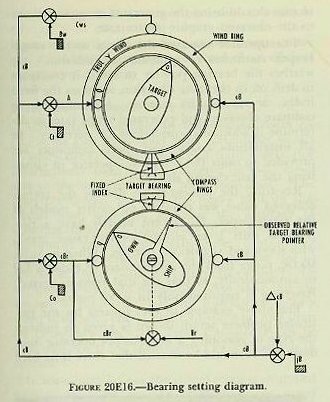
Since target bearing is generated in a manner similar to the generation of range, a disagreement between generated bearing (cBr) and Br will indicate that computed RdBs is wrong. (See figure 20E16.) When RdBs is wrong and dR is correct, as at position 1 in the diagram, the operator can adjust A and S to correct RdBs without changing dR, by maintaining the dial reading of dR at the value indicated before the adjustment is made. Similarly, dR can be corrected without changing RdBs if conditions require such an adjustment.
The analytical aspect of rate control has been considered thus far. The following is a brief discussion of the manner in which rate control is actually accomplished by the rangekeeper operator.
Referring to figure 20E16, the picture shown on the target and own-ship dials is merely an indication of the vectors for a typical example.
From the figure, it can be seen that the observed bearing as given by the pointer is farther to the right than the generated value which is read opposite the fixed index above own-ship dial. This indicates that the generated and observed bearing rates do not agree. If at the same time the generated range (see range-rate dial, fig. 20E15) is compared with the rate given by the graphic plotter, the whole picture becomes evident.
Let us assume that the generated range rate is increasing at 15 knots, while observed range rate is increasing at 10 knots. These facts indicate that the generated Xt component is too small and the Yt component is too large. If the operator changes target course to the right, the Xt component will be increased and the Yt component decreased, both of which are desired. If the operator increases target speed, Xt will be increased; but Yt, which is already too large, will be further increased. In the situation shown, target course is the dominant element and should be changed first. Before making a course change, however, the operator should ensure that present range (as shown in window at the lower left-hand corner of the rangekeeper face) is correct, if hand input is being used, and that the observed bearing pointer is reset opposite the fixed index.
In resetting bearing, reference to figure 20E16 will show that all dials will turn together when jB is changed, and thus the present setting of target angle will be thrown off. For instance, after the observed-bearing pointer is reset on the fixed index, target angle will read roughly 180°, instead of 160° as it does in the figure. By use of the target-course crank it must be returned to its original value, 160°, and then the additional corrective change to the right, to about 140°, should be made. This change should bring the generated range rate closer to the observed graphic-plotter rate.
The operator observes the set-up as the rangekeeper continues to generate the solution. He watches the bearing pointer to see if it continues to drift off in the same direction, stops on the fixed index, or reverses its motion. He continues to compare observed and generated range rates to determine if additional corrections are necessary. In all installations course and speed indicators are provided to assist the computer operator in visualizing the rate control situation.
Resetting the present-range dial to the correct observed value was required on earlier models of the rangekeeper, but recent models have a two-position shift lever on the present-range crank, with HAND and AUTOMATIC settings. When in AUTOMATIC, range from the rangefinders or radar is fed in automatically, so that the dial remains correct. Resetting is required only in HAND position.
The above example of rate control for the particular problem set-up shown is given to indicate the type of reasoning a rangekeeper operator must develop. It should be stressed that there is no hard and fast rule for the amount of change to make in Ct and S to obtain the proper solution. Long hours of practice in tracking actual targets alone will provide the experience required of an efficient rangekeeper operator.
20E8. Gun train order relay transmitter
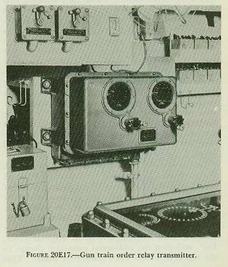
Additional equipment in the plotting room includes the gun train order relay transmitter shown in figure 20E17, which relays gun train orders (for information) from the rangekeeper or aloft directors to the multiple turret train indicators. The relay transmitter prevents the heavy load on this circuit from adversely affecting the accuracy of transmission of gun train order to the guns. The instrument receives gun train order (indicating) from either the rangekeeper or the director (or in divided fire from both) and relays this order to the multiple turret train indicators. Normally this operation is automatic, but the instrument is provided with hand cranks and follow-the-pointer dials for emergency use. The relay transmitter can be used only when the main-battery switchboard is in operation.
In some installations the rangekeeper is equipped with a one-speed synchro transmitter for turret train information in addition to the usual two sets of synchro transmitters for gun train order (automatic) and gun train order (indicating). In such installations no separate gun train order relay transmitter is required nor provided.
20E9. Radar equipment
The Mark 13 radar equipment is used to measure range in the main-battery fire control system. Range measurement is controlled by the radar range operator in the plotting room. From the Mark 13 radar console, range is transmitted to remote range and train indicators in the director, in the plotting room, and in topside control stations. The radar equipment may also be used for training the director in automatic control under conditions of poor visibility, since it has a narrow, well-defined beam and good accuracy in bearing discrimination. See figure 20E18.
20E10. Main-battery switchboard
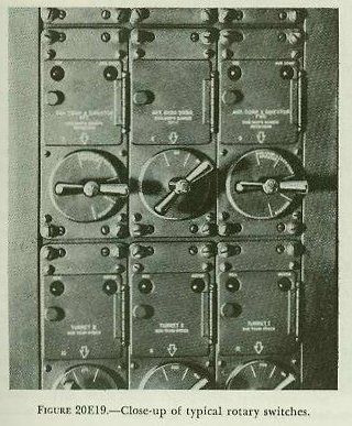
The plotting-room fire control switchboard is shown in figure 20E2. The board consists of five panels of type-J rotary switches, a fuse panel, and a snap-switch panel for the interior communications circuits. Figure 20E19 shows typical rotary-switch units.
The switchboard serves as a central point at which the synchro receivers and synchro transmitters in the various instruments and equipment comprising the fire control system can be energized and connected together as required for operation in different methods of fire control. Selections of signals to and from various elements of the system can be made, and substitute and alternate circuits can be set up in the event of casualties to some part of the system.
20E11. Miscellaneous equipment
Multiple turret train indicator. The plotting room contains one MTTI (see fig. 20E1), which shows the train of each of the three turrets and the difference between modified turret train response and gun train order. This instrument is the same as those used in the fire control stations.
Bearing indicator. This device (see fig. 20E1) indicates true target bearing, relative target bearing, and own-ship course. It is used for information purposes and is the same as those used in the fire control stations.
Dead-Reckoning Tracer Mark 6. This instrument, shown in figure 20E2, is a plotting table with a pencil mechanism for charting own-ship course. North-south and east-west distance components, received from the analyzer of the dead-reckoning system, actuate the motors and mechanisms which drive the pencil carrier to record a graphic plot of the ship's travel and also drive the dials which indicate the latitude and longitude. A clock mechanism is electrically connected to the pencil carrier to record elapsed time on the graphic plot. Any point defined by range and true bearing may be plotted relative to own ship on the plotting board. The equipment is used during shore bombardment operations.
Director train indicators. Two director train indicators, shown in figure 20E20, are mounted on the plotting-room bulkhead. These instruments show the train angle of the forward and after main and secondary battery directors.
Ready lights. The plotting room contains numerous salvo signal lights, turret ready lights, and other signals to provide visual information from other stations.

20E12. Auxiliary main-battery switchboard
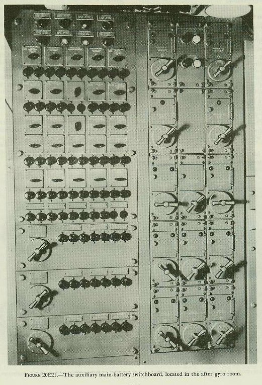
In the event of casualties to the main-battery switchboard, gun orders can be routed from the directors to the turrets via the auxiliary switchboard. This board is located in the after gyro room and is connected with directors 1 and 2 and with turrets 1 to 3 by cables run in separate wire-ways widely separated from the primary cables. In order to shift control of the system to the auxiliary main-battery switchboard, switches located at the fire control stations and turrets are shifted from MAIN to AUX position.
The board consists of one switch panel and a snap switch and fuse panel. Indicator lights show the division of battery control between the directors. Type-J selector switches control the routing of gun orders and other data for the fire control installation. Figure 20E21 shows the front of the switchboard.
F. Turret Fire Control Equipment
20F1. General
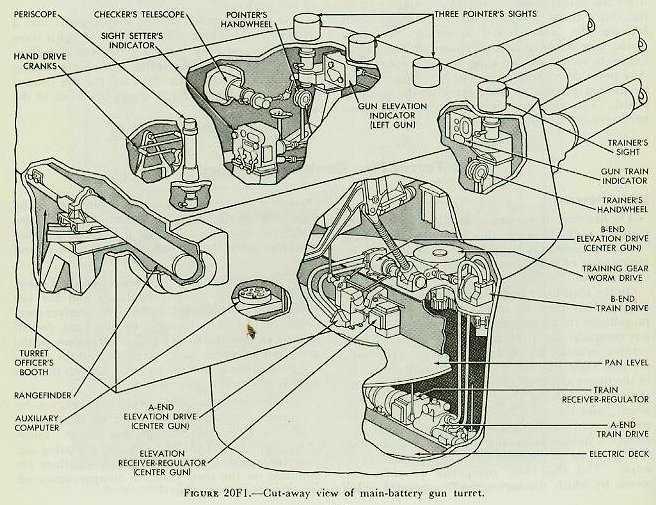
The fire control equipment installed in the turret is shown in the cut-away view of figure 20F1. Part of the equipment is located on the shelf plate, or upper level of the turret, and the rest on the two decks below.
On the shelf plate at the rear is the turret officer's booth. This space contains the rangefinder and the rangefinder stabilizer, the spotter's periscope, auxiliary computer, multiple turret train indicators, and various switches and indicating lights. Forward, are four sight stations, one on each outboard side of the turret and two between the guns. The right station contains the trainer's periscope and handwheels, and the train indicator. The other three stations contain the periscopes, handwheels, and elevation indicators for the three pointers, one for each gun. At the extreme left is the checker's periscope. The shelf-plate equipment provides the means by which the turret can be operated independently of the rangekeeper and directors. The sights enable the target to be located; the rangefinder measures the range to the target; and the computer solves the fire control problem for Vs and Ds.
On the pan floor, one deck below the shelf plate, are the elevation receiver-regulators and the elevating gear A-ends and B-ends. The receiver-regulators control the elevation of the guns (which operate independently in elevation) in response to the gun elevation order (auto and local), and the elevating gears actually move the guns. Also on the pan floor is the training-gear B-end.
On the next lower deck, the electric deck, are the train receiver-regulator, which controls the training of the turret, and the training-gear A-end. Emergency hand cranks for training and elevating the guns manually in the event of power failure are mounted on the shelf plate, in compartments adjacent to the wing guns.
20F2. Rangefinder
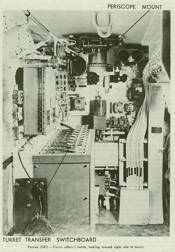
The rangefinder passes through the turret officer's booth in back of the beam at the upper right of figure 20F2. Turrets 2 and 3 are equipped with rangefinders of the erect-image stereoscopic type and are capable of measuring ranges from 2,500 to 50,000 yards. The base length is 26 feet 6 inches, and the magnification is 25 diameters. The rangefinder in turret 1 is of the erect-image, coincidence type, with the same base length and magnification.
Sighting through the main eyepiece, the rangefinder operator adjusts the measuring knob to keep the wander mark on the target in the stereoscopic type of rangefinder, or to match the two images in the coincidence type. The operator then presses the switch in the center of the measuring knob, which sends an electrical signal designating the range to the rangekeeper. Range may also be read from the range scale and transmitted by phone (JW circuit) to the rangekeeper operator. Besides the main eyepiece there is a rangefinder trainer's eyepiece, used for locating and centering the target in the main instrument field.
The rangefinder stand supports the rangefinder in two saddle bearings, which permit the rangefinder tube to be rotated through 30 degrees. The stand also permits deflection of the rangefinder 5°30′ left or right of the line of the gun bore, to nullify the deflection of the guns from the line of sight.
The rangefinder is stabilized in level — that is, its line of sight is held horizontal as the ship rolls — either by means of a hand lever or by the rangefinder stabilizer. The latter device consists of a gyroscope, which activates an electric-hydraulic follow-up system to keep the rangefinder level. A clutch handle is provided to shift from hand to automatic stabilizing.
20F3. Periscope
Figure 20F2 shows the periscope mounted in the roof of the turret, which serves for general lookout purposes; for picking up targets; for estimating their range, course, and speed; and for spotting the fall of shells.

20F4. Auxiliary computer
The Computer Mark 6 shown in figure 20F3 is a standby instrument intended for use only when the turret is isolated by casualties. It is located at the right side of the turret officer's booth and operates without mechanical or electrical inputs to compute Vs and Ds. It will not be described here.
Because some of the refinements of calculation found in Rangekeeper Mark 8 are omitted from the design of the auxiliary computer for compactness and to permit the use of the computer independently of the major control systems, the solution obtained with it is not as accurate as with the more complex instrument.
20F5. Multiple turret train indicator
The turret officers' booth contains an MTTI similar to those in the plotting room and fire control stations. Turrets 1 and 2 each contain a train indicator showing turret train and gun train order for turrets 1 and 2; turret 3 contains an indicator showing such data for own turret only.
20F6. Eight-inch sight
The turret sight consists of the trainer's, checker's, and the three pointers' periscopes and the shafting which connects them with the sight setter's indicator and the gun attachments. The sights are used to aim the guns in LOCAL, and to check the aim in other methods of gun laying.
As the trainer trains the turret to bring the vertical crossline on the target, and the pointers elevate the guns to bring the horizontal crosslines on the target, the gun bores are deflected both horizontally and vertically from the line of sight according to the sight angle and sight deflection set in by the sight setter.
The line of sight of all the sight telescopes may be deflected 110 mils right or 90 mils left of the gun axis, and the pointers' and checker's telescopes may be elevated 1° above or depressed 41° below this axis. Stops on the foot treadle and hand lever of the trainer's sight permit 18° movement above and below a plane parallel to the roller path of the turret.
As previously mentioned, the turret sight is used primarily for positioning the turret guns in local gun laying. However, in those methods of gun laying where the sight is not directly employed, the telescopes are continuously positioned by the combined action of the sight setter and gun elevation response, so that they may be used for checking purposes, and so that they may be in constant readiness for change-over to local control if necessary.
20F7. Sight setter's indicator

The sight setter's indicator, shown in figure 20F4, is located abaft the center pointer's station in each turret and serves as a range, sight-angle, and sight-deflection indicator. The sight setter's indicator receives two electrical inputs: sight angle and sight deflection. By turning cranks on the front of the instrument to match the outer dial with the inner electrical dials, these quantities are transmitted mechanically to the sights. Sight angle is also transmitted by shafting to the gun elevation indicators and receiver-regulators, where it is used in the erosion-correction mechanisms.
The sight setter's indicator contains a parallax range scale and crank, and a range scale. By turning the parallax-range crank to set in the range read from the range scale, the sight setter transmits parallax range to the train indicator and the train receiver-regulator, where it is used in computing the parallax correction. Since sight angle is a function of range for a given muzzle velocity, it can be converted to range. This is done by the range scale, which is driven according to the sight angle set in the instrument, but which is graduated to read range.
The sight setter's indicator is used to set the sights in all methods of gun laying and of turret drive. In addition, it supplies mechanical inputs of sight angle and parallax range respectively to the elevating and training equipment, for the purposes noted, in both automatic and indicator gun laying.
20F8. Training equipment
The training equipment consists of the trainer's handwheels, the gun train indicator, the train receiver-regulator, the training speed-gear A-end and B-end, and accessory equipment.
The turret is trained by means of the training speed gear controlled by the train receiver-regulator or the trainer's handwheels.
The trainer's handwheels may be connected by means of a clutch to the tilting plate of the training-gear A-end, or to the receiver-regulator. The trainer operates his handwheels either to bring his vertical crossline on the target (in local gun laying) or to match the dials of the gun train indicator (in indicator gun laying).
20F9. Gun train indicator and transmitter
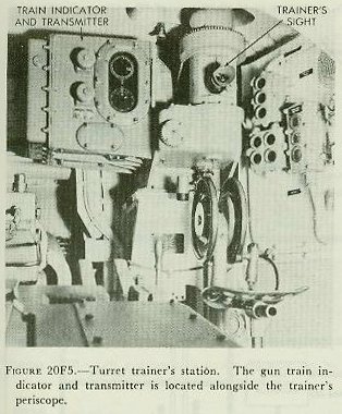

The gun train indicator, shown in figure 20F5, is located at the trainer's station on the right side of the turret. The instrument receives gun train orders on synchro receivers. It is used in indicator gun laying to guide the trainer in operating his handwheels so that these orders are carried out. One synchro receiver operates a zero-reader dial; the other a follow-the-pointer dial. The instrument mechanically receives turret train response from the training gear, and parallax range from the sight setter's indicator. Parallax range and turret train response operate the parallax corrector, which computes the correction for parallax. This correction is introduced into turret train response by means of a differential to produce modified-turret train response, which operates the outer dial of the follow-the-pointer dials, and restores the zero-reader dial to zero. Turret train response is displayed on dials for comparison with the electrical order dials, and is transmitted electrically by synchro transmitters to the MTTIs in various stations in the ship. In automatic gun laying the gun train indicator is not used to control the turret, but still indicates gun train order and modified turret train response, and transmits the latter to the MTTIs.
20F10. Train receiver-regulator
The train receiver-regulator, shown in figure 20F6, is located on the electric deck.
It controls the training gear in accordance with an electric gun train order. The instrument has three inputs: gun train order (received electrically from the plotting room or auxiliary switchboard, or mechanically from the trainer's handwheels, depending on the method of gun laying employed); parallax range, received mechanically from the sight setter's indicator; and turret train response, received mechanically from the training gear. Within the regulator, turret train response is corrected for horizontal parallax and matched with gun train order. The difference between the actual and ordered positions of the turret creates an error signal which is amplified and used to control the training speed gear in such a manner that the turret is automatically trained to the ordered position. The train receiver-regulator operates normally in response to remote or local signals.
20F11. Training speed gear
The turret is trained by the hydraulic training gear, which consists of a motor-driven pump (A-end) and a hydraulic motor (B-end). Part of the gear can be seen in figure 20F6. The hydraulic motor drives a pinion which engages with a stationary rack mounted on the barbette. As the pinion rolls around this rack, the turret is carried with it. Speed and direction of rotation depend upon oil flow from the A-end, which in turn is controlled by the train receiver-regulator or mechanical handwheel drive.
In the event of power failure, the turret may be trained by manual power. The training-gear A-end is connected through a clutch to two handcranks located on the shelf plate. By engaging this clutch the A-end may be driven by turning the cranks instead of by the motor. This form of operation is called manual drive. In manual drive, the training of the turret is controlled by the trainer's handwheels in the same manner as when power is used, but the training rate attainable is, as might be expected, much slower.
20F12. Operation of training equipment
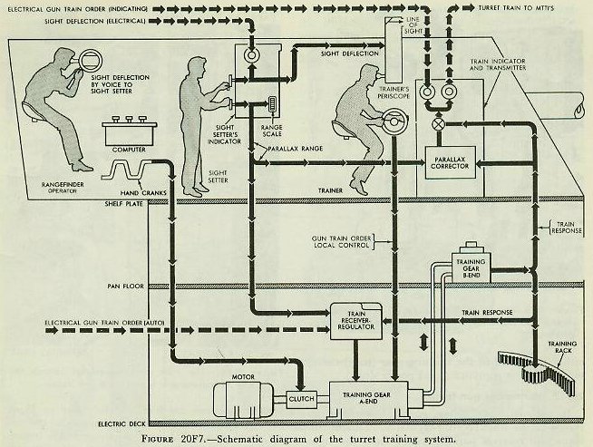
Figure 20F7 is a functional diagram of the turret training system, showing the instruments described above. The path of quantities in the various methods of gun laying can be traced on this diagram.
20F13. Local gun laying
Local gun laying is used in local fire control. The target is located by means of the turret periscope, and the turret is trained until the target can be seen in the turret sights. Range, as measured by the local rangefinder, and turret train from the MTTI are set into the computer as hand inputs, and with these data, and the other hand inputs, a value of sight deflection is computed. This computed sight deflection is sent to the sight setter by phone, and he cranks the value into his sight setter's indicator, thus deflecting the pointer's and trainer's sights. The trainer operates his handwheels to keep his vertical crosslines on the target, and thus deflects the gun by the amount of the deflection angle turned into his sight. In local fire control no horizontal parallax correction to turret train is necessary.
In primary, secondary, and auxiliary fire control the turret may be trained in either indicator or automatic gun laying.
20F14. Indicator gun laying
In indicator gun laying, turret train response is corrected for parallax in the gun train indicator and compared with the gun train order on the dials of that instrument. Observing the dials, the trainer trains the turret in accordance with the orders received. Training of the turret is accomplished by means of the trainer's handwheels, which control either the A-end of the training gear (hand drive) or the receiver-regulator (local power drive).
20F15. Automatic gun laying
In automatic gun laying, gun train order is received by the train receiver-regulator. This instrument also receives parallax range from the sight setter's indicator and turret train response from the B-end of the training gear. Combining these inputs, the receiver-regulator automatically controls the A-end of the training gear so as to bring the turret to the ordered position. In automatic gun laying the gun train indicator transmits corrected turret train to the multiple turret train indicators throughout the system.
20F16. Elevating equipment
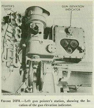

The elevating equipment is similar in fundamental principles and operation to the training equipment. It consists of the pointers' handwheels, gun elevation indicators, elevation receiver-regulators, and the elevating speed-gear A-ends and B-ends. Each of the guns is elevated independently by its elevating gear, which is controlled either by the elevation receiver-regulator or by the pointers' handwheels, depending on the method of gun laying employed. The handwheels may be connected through a clutch to the tilting plate of the elevating gear A-end, or to the receiver-regulator. The pointer operates his handwheels either to bring the horizontal crossline of his telescope on the target, or to match dials on the gun elevation indicator. Figure 20F8 shows a view of the left pointer's station.
20F17. Gun elevation indicator
The gun elevation indicator functions in a manner similar to the gun train indicator. One of these is shown in figure 20F8 at the left pointer's station. In indicator gun laying the gun elevation indicator receives gun elevation order electrically and gun elevation response mechanically. These values are indicated on the zero-reader and follow-the-pointer dials and are used by the pointer in elevating the gun in follow-the-pointer operation.
Before gun elevation response is compared with the order, two corrections are made within the indicator to the response signal. These are (1) roller-path tilt correction, and (2) erosion correction.
Roller-path tilt correction compensates for inclination of the turret's roller path plane with respect to the ship's reference plane for any angle of train of the turret. This correction varies with the position of the turret in train and with the inclination of the roller path. The inclination of the roller path is determined when the battery is aligned, and is set into the roller-path tilt mechanism by screw-driver adjustment. Train is received from the training gear. A computation based upon two inputs produces roller-path tilt correction for the particular train angle.
Erosion correction compensates for the reduced initial velocity of the projectile due to the erosion of the gun barrel as successive charges are fired. The effect of gun erosion on the trajectory varies with the range, which is a function of sight angle and the initial velocity of the projectile. The erosion corrector thus receives two inputs: sight angle, which provides the range function, and a hand input to account for the velocity loss. The usual practice is to put an initial velocity setting into the rangekeeper in Plot, or into the auxiliary computer in the fire control station, equal to that for the least eroded gun in the battery. A value of initial velocity loss, equivalent to the difference between the velocity set into the rangekeeper or computer, and the actual velocity obtained in the individual gun, is then set into each gun elevation indicator by means of the velocity-loss knob. A velocity-loss dial is provided to enable the operator to read the value of velocity loss introduced. Erosion correction and roller-path tilt correction are added (algebraically) to gun elevation response to produce modified gun elevation.
Summarizing, the inputs to the instrument are: gun elevation orders, electrical; turret train, for the roller-path tilt correction; sight angle and velocity loss for the erosion corrections, and elevation response from the gun elevation attachment.
20F18. Elevation receiver-regulator
The elevation receiver-regulators control the elevating gears in accordance with gun elevation order. This order comes from the plotting-room switchboard or auxiliary switchboard, or from the pointer's handwheels. One of these instruments is shown in figure 20F9 located on the pan floor, beside the elevation A-end.
The elevation receiver-regulator, like the train receiver-regulator, is an electric-hydraulic follow-up device. It controls the A-end of the elevating gear. The unit has correction mechanisms to correct gun elevation response for roller-path tilt and erosion, and to compensate for the non-linear relationship between elevating-screw rotation and gun elevation. The first two corrections are the same as those made in the gun elevation indicator. The receiver-regulator has a velocity-loss knob and dial, by means of which velocity loss may be set into it, in a manner similar to that for the elevation indicator. It also receives sight angle from the sight setter's indicator for computing erosion correction and turret train response from the training speed-gear B-end for computing roller-path tilt correction.
The elevating-screw correction compensates for the disproportionality between rotations of the elevating-screw nut and rotation of the gun about its trunnions. It should be noted that this correction is not necessary in the gun elevation indicator, because the elevation response input to this instrument is driven from a gear segment fastened to the gun, instead of from the elevating-screw drive; hence the proportionality of gun movement and response is constant for all gun elevations.
Gun elevation response, when corrected, is compared with gun elevation order, the difference between the two producing an error signal. This error signal controls the A-end of the elevating gear in such a way as to drive the gun to the ordered position.
A control selector at each pointer's station is connected to the receiver-regulator by shafting. When thrown to LOAD, the selector positions hydraulic valves so as to bring the gun rapidly to the loading position after it has been fired. An auxiliary selector at the pointer's station can be positioned to transfer loading control to the gun captain, which is the normal procedure. The gun captain may then exercise control by means of his ready switch. Return of the pointer's selector to AUTO, or of the gun captain's switch to READY, causes the receiver-regulator to reposition the gun at the existing value of gun elevation order.
20F19. Elevating gear
Each gun is elevated by an elevating screw which travels through a nut rotated by the B-end of the elevating gear. Part of an A-end may be seen in figure 20F9. The gear consists of a hydraulic pump and motor similar to the training gear, and is controlled in the same way.
In manual drive, the A-end of the elevating gear may be connected, through a clutch, to the same hand cranks used for the training gear. The same clutch disconnects the electric motor. In manual drive, elevation is slower than in other methods.
20F20. Operation of elevation equipment

Figure 20F10 shows a functional schematic of the operation of the elevation system. There are three duplicate sets of elevation equipment — one for each gun — only one of which is shown. The equipment is located on the shelf plate, at the pointers' stations, and on the pan floor.
20F21. Local gun laying
In local gun laying, as explained in article 20F13, the computer furnishes the values of sight angle and sight deflection. Sight angle is received by phone from the computer operator and set into the sight setter's indicator by the sight setter. Motion of the hand crank moves the line of sight in relation to the gun bore. Sighting through the telescopes, the pointers operate their handwheels to position the guns until the horizontal crosslines are on the target. The handwheels control either the A-ends of the elevating gears (hand drive), or the receiver-regulators (local power drive).
If manual drive is used, the operation is the same, except that manpower is supplied to the A-end from the hand cranks instead of electric power from the motor.
In primary, secondary, and auxiliary fire control, the guns are elevated in accordance with an electrical gun elevation order. In each case, the guns may be elevated in either indicator or automatic gun laying.
20F22. Indicator gun laying
In indicator gun laying the gun elevation order positions the follow-the-pointer inner dials of the gun elevation indicators. The pointers operate their handwheels to match the dials. By so doing they control the A-ends of the elevating gears, which control the elevation of the guns. The elevation of each gun is transmitted mechanically from the elevating arc as elevation response back to the gun elevation indicator. Here the elevation corrections are added to gun elevation response to produce modified gun elevation, which restores the zero-reader dial and positions the follow-the-pointer ring dial.
In auxiliary fire control, sight angle is not available on the dial of the sight setter's indicator, but must be supplied by the local computer or from some other source by telephone.
20F23. Automatic gun laying
In automatic gun laying the gun elevation order is received by the elevation receiver-regulators, which automatically control the A-ends of the elevating gears, and thus the elevation of the guns.
The receiver-regulators also receive sight angle and velocity loss for computing the erosion correction, and turret train response for computing the roller-path tilt correction, as do the elevation indicators.
20F24. Turret inputs and outputs
The quantities received by the turrets are:
1. Gun train order (automatic, indicating).
2. Gun elevation order (automatic and indicating).
3. Sight angle.
4. Sight deflection.
5. Adjacent turret train (in turrets 1 and 2).
The outputs are:
1. Turret train (information).
2. Optical range.
Some of the types of fire control which may be used were briefly discussed in article 20B4. Figures 20F11, 20F12, and 20F13, which are flow diagrams for primary, secondary, and local fire control respectively, should assist in an understanding of what takes place in these types of control.
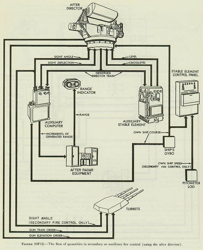

G. Main-Battery Radar
20G1. General
Two radars are used with present-day main-battery fire control installations. These are Radar Equipment Mark 13 Mod 0 and Radar Equipment Mark 8 Mod 3. Although the Mark 13 has almost completely replaced the Mark 8 Mod 3 in the Fleet, the Mark 8 Mod 3 may still be found on some ships. Therefore a short description of this radar is given later.
In studying this section the student may find reference to chapter 16 helpful.

20G2. Cruiser radar installation
The majority of cruisers now in commission have two Mark 13 radars installed, one for use with each of the two Mark 34 directors. The antenna, which scans by rocking back and forth horizontally, is mounted on top of the director (fig. 20G1), and the radar transmitter-receiver is located inside the director.
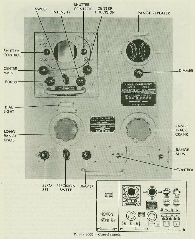
The main radar control unit for the forward Mark 13 radar is located in the main-battery plotting room near the Mark 8 rangekeeper. This unit, known as the control console (fig. 20G2), is controlled by the radar operator. The control console for the after radar is located in the after main-battery control station topside, adjacent to the Mark 3 auxiliary computer. The radars are normally operated from the control consoles. However, provision is made for shifting control of either radar from the console to a remote-control unit (fig. 20G3) at the control officer's station in the associated director.
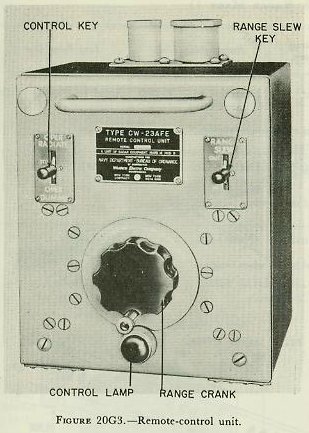
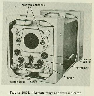
Two remote range and train indicators (fig. 20G4) are located in each director, one to aid the trainer in getting on target by radar, and one to provide the control officer with continuous target data and to enable him to spot fall of shot.
In addition, two remote range and train indicators, one for each radar, are installed adjacent to each main-battery rangekeeping instrument — the Mark 8 rangekeeper in the plotting room, the Mark 3 computer in the forward topside control station, and the Mark 3 computer in the after topside control station. These remote indicators give the same B-scope presentations seen on the control consoles, and associated range counters give direct range readings for use of the rangekeeper or computer operator. Fall of shot may also be spotted from remote indicators.
Other components of the radars are below decks.
20G3. Beam characteristics
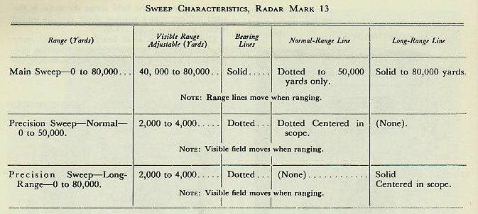

Figure 20G5 illustrates the radar beam of the Mark 13 radar. This beam consists of a series of pulses emitted at the rate of 1,800 per second, each pulse lasting 0.3 microsecond. Since radio energy travels at a constant speed of 328 yards per microsecond, the pulses theoretically are about 100 yards long or are represented by a 50-yard range interval on the scope, since scope presentations are for round trips of the pulses. The time interval between emission of pulses is 555 microseconds. Since the time required for a pulse to travel out 80,000 yards and return is 488 microseconds, there is ample time for each pulse to travel the maximum range and return before the next pulse starts.
In Radar Equipment Mark 13 Mod 0 the beam is 0.9° wide and 3.6° high. Actually, the radar beam is not as sharply defined as appears in figure 20G5. It is strongest at points along its axis, becoming weaker as the angular distance from the axis increases.
20G4. Scanning
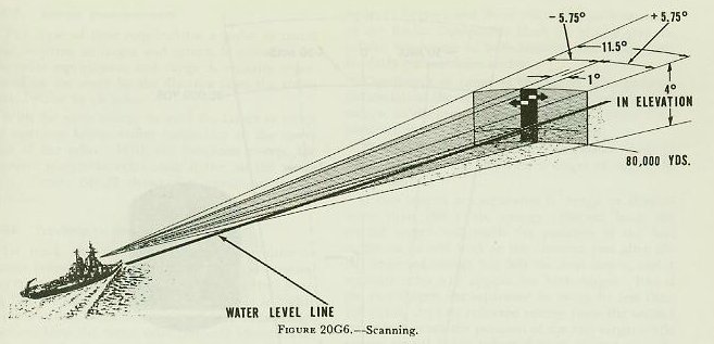
In scanning (fig. 20G6), the rocking antenna mounted on top of the director causes the narrow beam to progress back and forth through a horizontal arc of 11.5° (200 mils) five times in each direction per second. The center of the scanning arc is rigidly aligned with the director line of sight, so that when the director is trained on a target, accurate bearing indication is given by the radar. With respect to the bearing of the director, the radar beam scans an area between +5.75 and −5.75 degrees.
Note: Positive (+) signifies increasing bearing, and negative (−) signifies decreasing bearing.
20G5. Scope presentation
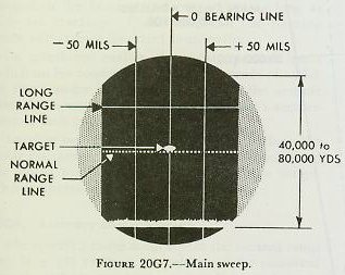
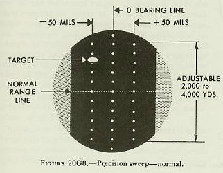
The scope presentations seen on the control console and on the remote range and train indicators are identical, and are B-type presentations. In this type of presentation, own ship is at the bottom of the scope, and the picture seen is that of a narrow, wedge-shaped segment of the earth. Figures 20G7 and 20G8 show the appearance of the scopes, both on the control console and on the range and train indicators, when set to MAIN SWEEP and when set to PRECISION SWEEP–NORMAL. Whenever the radar equipment views a target, a bright spot (the echo from the target) appears on the scope. The centerline or zero bearing line is aligned with the line of sight of the director. The distance between vertical lines represents intervals of approximately 50 mils in bearing. When the field of view starts at zero yards, the wide horizontal line at the bottom of the scope marks the outgoing pulse. All ranges are measured upward from this horizontal line. The narrow dotted and solid horizontal lines are called the normal-range line and the long-range line respectively. They are independent of each other; their operation is described in the following paragraphs.
20G6. Types of sweep
There are available in the Mark 13 radar three types of sweep: main sweep, precision sweep-normal, and precision sweep-long-range.
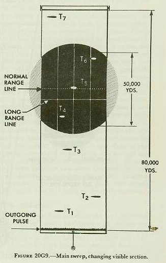

Main sweep. On main sweep the operator can view out to 80,000 yards. The total range appearing on the scope (fig. 20G9) may be varied from 40,000 yards to the entire 80,000 yards. It is recommended that the field of view be set to 50,000 yards (fig. 20G10). The operator can then view any 50,000-yard section of this 80,000 yards by adjusting the center main control (see fig. 20G2) on the console, which moves the field across the scope in the same manner that a window shade may be moved behind an opening (fig. 20G9).
There are three solid bearing lines, the outer lines each 50 mils out from the center bearing line. The total width of the scope is approximately 200 mils, 100 mils either side of the center bearing line.
Two range lines are visible on main sweep. The long-range line, which is solid, is controlled by the long-range knob, and moves over the face of the scope to the maximum of 80,000 yards. The normal-range line, which is dotted, is controlled by the range-track crank and moves over the face of the scope only to 50,000 yards. The operator shifts the range line until it touches the bottom of the echo. The range to the target can then be read from the long-range dial or the range repeater.
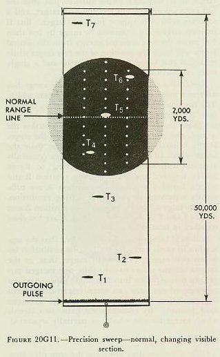
Precision sweep-normal. On precision sweep the operator can view to a maximum of 50,000 yards, but only 2,000 to 4,000 yards of this at a time. The desired visible field on precision sweep, which may be any value between 2,000 and 4,000 yards, is set by an internal adjustment and usually is not changed by the operator. In this discussion it is assumed that the selected field visible on the scope is 2,000 yards (fig. 20G11). The operator can select any 2,000- to 4,000-yard section out of the normal 50,000 yards available. This is done by operating the range-track crank, which moves the visible field in the scope in the manner of a roller shade. The range line is dotted and fixed in the center of the scope. Note that on precision sweep the field, and not the range line, moves during ranging. When the echo rests upon the range line, range to the target can be read from the range repeaters. Bearing lines are made up of dots indicating spaces 200 yards apart.

Precision sweep-long range. The long-range unit can be used with precision sweep out to 80,000 yards, but range must be read from the long-range dial with its coarse graduations, and will not be as accurate as with the normal-range unit, the range reading dials of which have graduations as small as 10 yards. Precision sweep-long-range is used for observation only; range is not transmitted to the rangekeeper. In this case the solid long-range line is also fixed in the center of the scope.
A recapitulation of sweep characteristics of Radar Equipment Mark 13 Mod 0 is given in the table above.
20G7. Range measurement

The lapse of time required for a pulse to travel from antenna to target and return is measured by the radar equipment, and range is visually represented on the scope by the distance from the transmitted pulse to an echo.
With the main sweep, to track the target in range the operator brings either range line to the lower edge of the echo. With the precision sweep, the operator moves the echo until it lies on the range line. Figure 20G13 shows the correct setting of an echo.
20G8. Tracking in bearing
To track the target in bearing, the director trainer (viewing his remote range and train indicator) trains the director until the zero (center) bearing line on the scope bisects the echo. It is highly important that both the trainer and the radar-range operator keep the target echo properly located with respect to the bearing and range lines as long as they are tracking. Unless they do, the plotting room will receive incorrect information.
As mentioned earlier, the radar operator has a switch on his console (fig. 20G2), by means of which he can transfer ranging control from the console (switch on LOCAL) to the director officer's remote-control unit (switch on REMOTE).
Another switch on the control console allows the radar operator to quickly align the target echo and the range line when first picking up the target. This is known as the range slew switch.
20G9. Accuracy and resolution
The specified range accuracy for the normal range unit is ± [15 yards + 0.1 percent of the measured range], and for the long-range unit is ± 1.0 percent of the measured range. Therefore, with the units ranging on target at 3,000 yards the normal-range unit will be accurate to within ± 18 yards, the long-range unit to within ± 30 yards; and on a target at 30,000 yards, the normal-range unit will be accurate to within ± 45 yards, the long-range unit to within ± 300 yards. Advantage can be taken of the higher range accuracy of the normal-range unit out to a maximum of 50,000 yards.
Target bearing accuracy is ± 0.1 degrees (2 mils), or better. If exact alignment were possible, an accuracy of ± 1 mil might be attained.
Resolution — that is, the minimum separation between two targets in order that accurate range and bearing of either target may be obtained — depends upon beam width and pulse length. The narrow beam (1 degree) and short pulse (0.3 microseconds) of the Radar Equipment Mark 13 Mod 0 give excellent resolution in both bearing and range, particularly on precision sweep.
The length in range of the target echo gives an indication of the minimum separation between two targets on the same bearing which will permit complete resolution of those targets in range.
This echo length on Radar Equipment Mark 13 Mod 0 is about 100 yards for a target of negligible range depth.
If two targets are separated in range by slightly more than 100 yards, energy reflected from the second target will reach the position of the first target on its way back to the antenna just after the last reflected energy has left the first target, and a separate echo will appear for each target. But if the two targets are separated in range by less than 100 yards, the first reflected energy from the second target will reach the position of the first target while energy is still being reflected from it, and a single large echo will appear.
Resolution of two targets at the same range but different bearings depends upon the beam width. The beam width is approximately 1 degree. Therefore, if two targets are separated by more than 1°, the beam leaves the first target before it strikes the second, and two echoes will appear upon the scope. If the separation of two targets is less than the beam width of 1°, a single wide echo (generally asymmetrical) will appear. Referring to figure 20G14, targets 1 and 2 as seen from position B and targets 3 and 4 as seen from position A are sufficiently separated to give good bearing resolution, whereas targets 3 and 4 as seen from position B and targets 1 and 2 as seen from position A are too close together in bearing.
It should be apparent to the student that the separation in yards necessary for bearing resolution between two targets varies with range; thus, as the targets become closer to own ship, one merged target pip may separate into two single pips. Also, an experienced operator can often improve the bearing resolution by judicious use of the RECEIVER GAIN control. By reducing the gain, two signals which merge may be wholly or partially separated.

20G10. Distortion
Since a B-scope does not show the true plan-view relationship of targets but shows a pie-shaped segment of the earth's surface as a rectangle, the result is a picture somewhat distorted in range and bearing. As will be explained, distortion in bearing is not the same as distortion in range. In order to interpret B-scope presentations properly, the operator must be familiar with the effects of distortion; at the same time, however, it is important to remember that neither kind of distortion in any way affects the accuracy of range and bearing to a target whose echo is properly set on the range lines and bisected by the zero bearing line.
Range distortion. Range distortion is present in Radar Equipment Mark 13 Mod 0, since arcs of circles drawn from own ship as center appear on the scope as straight lines. However, because of the small angle (11.5°) through which the beam scans, range distortion is insignificant except at long ranges, and may be ignored.
Bearing distortion. The distortion in bearing is of much greater magnitude and therefore of greater importance to the radar operator concerned with the method of presenting the scanned surface area on the B-scope. Bearing distortion should be understood by all officers and operators, because all targets in the scanned sector within the range of the equipment will appear on the scope in a distorted plan view. The relationship of one target to another on the scope will depend upon the range of the targets. Where it is possible to see both the B-scope and a PPI at the same station (as in the fire control tower of large ships) the two indications will not necessarily be similar. The distortion is most apparent when shore lines, islands, or large groups of ships are involved. In shore bombardment problems this distortion will be of greatest importance. When B-scope charts of a target are drawn in advance from navigation charts, the effect of the distortion at the expected range must be included. The nature of this distortion will be clear when the factors discussed in succeeding paragraphs are understood.

An explanation of bearing distortion when operating on main sweep follows. Figure 20G15 shows the yardage visible on the screen at various settings of the main sweep. The yardage represented by the width of the screen at the top is proportional to the maximum range to which the main sweep is set. For example, when the main sweep is set to show a maximum range of 40,000, 60,000 or 80,000 yards, the total yardage visible in bearing at the top of the screen is 8,000, 12,000, or 16,000 yards, respectively. As you progress down, the bearing yardage decreases. Assume that the main sweep is set at 50,000 yards and that three target ships, each 2,000 yards apart, approach the radar ship on straight, parallel courses (fig. 20G15). As they advance, the echoes of the two outside ships will diverge until they leave the screen at approximately 20,000 yards, while the center echo will continue along the center bearing line. The intervals in bearing between targets in a group will therefore appear to vary with the range, as indicated in figure 20G15. The picture of groups of targets on the B-scope is distorted so that wrong conclusions might easily be drawn from optical viewing only. The picture on the B-scope gives somewhat the appearance of perspective in bearing, but there is no foreshortening in range. It is seen from this illustration that the reason for the bearing distortion is that radial bearing lines in the scanned sector are represented by vertical parallel lines on the B-scope. A wedge-shaped sector of the earth's surface is displayed on the scope as a rectangular area.

It should be particularly useful at this time to study in detail how varying linear values appear on the precision sweep for the same angle at different ranges. Precision sweep shows not the total range from the radar ship to the extreme of the sweep, but only the selected 2,000- to 4,000-yard range portion. The following discussion assumes the sector to be 2,000 yards. Figure 20G16 shows groups of targets at 20,000-, 10,000-, and 5,000-yard range and precision sweep's appearance when viewing each group of targets. The two targets at the same range are separated 1,000 yards in bearing. The target on the center bearing line is at 1,000 yards greater range than each of the two outer targets.
At 20,000 yards the width of the scope in bearing represents 4,000 yards, the interval in range 2,000 yards. A range interval of 1,000 yards covers the same distance on the scope as a bearing distance of 2,000 yards.
At a range of 10,000 yards the B-scope will show almost the true relative positions of the targets, because the 11.5° sector will be 2,000 yards wide, which is the same as the 2,000-yard range interval of precision sweep. Both the height and the width of the scope will represent 2,000 yards. Therefore, it is only at a range of 10,000 yards that the targets will appear substantially without distortion.
At a range of 5,000 yards, distortions will be in the other direction. The width of the scope now represents 1,000 yards, and the vertical distance 2,000 yards.
20G11. Interference
Several types of interference may be encountered in the operation of the Mark 13 radar. Among these are:
Double echoes. It is possible, especially when ranging on strong echoes from nearby targets, that secondary (ghost) echoes may appear on the screen. This is due to the reflected energy from the target ship hitting the radar ship and being reflected a second time from the target ship. The operator should become familiar with this phenomenon by observing such targets on a practice run. These ghost echoes will always appear at twice the range of the original targets, and may be distinguished by observing the range of the echo and its appearance as compared to the original echo.
Shore interference. When observing shore lines, there will be a small area (generally of negligible importance with the excellent discrimination of the Mark 13 radar) in which targets may be obscured by land background.
Minor lobes and nearby objects. The power from the antenna radiated in the minor lobes is small compared with that in the major lobe. Nonetheless, minor lobes may cause echoes from a large target close to the equipment. In a horizontal line across the screen will be one bright echo and several dimmer ones. It is characteristic of minor-lobe echoes that they all will be at exactly the same range and will fluctuate together with the main echo.
A small target with poor reflecting surface at close range may also send back weak echoes. It is therefore possible that, if a strong echo and one or more weak echoes are observed at exactly the same range, it may be assumed that the minor lobes cause the weaker signal. Careful checks should be made to prevent misinterpretation of such an occurrence.
Interference from other radars. Other radars operating in the vicinity may produce a background noise on the scope which will not, in general, affect operation.
Sea return. At times, particularly in stormy weather, large, irregular, and fluctuating pips may appear on the screen. This is called sea return, and is caused by echoes from waves. Reducing the receiver gain will eliminate much of the sea return and tend to sharpen the outlines of the target echoes.
20G12. Spotting
The Mark 13 radar can be effectively used to spot fall of shot in both range and deflection. Shell splashes appear on the B-scope as fluctuating echoes which last for several seconds, depending upon the size of the projectile and the range. Salvos produce larger or multiple echoes on the scope.
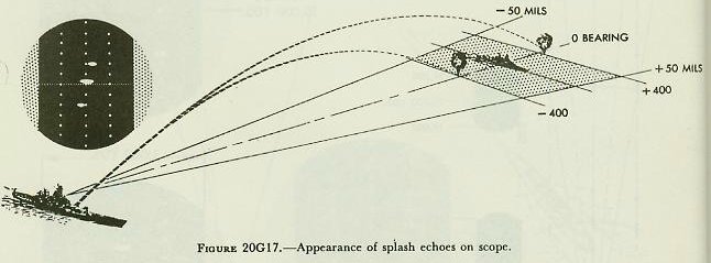

Radar spotting has proved to be both accurate and reliable to the full range of the guns and is, of course, independent of visibility conditions. In using the B-scope for spotting, precision sweep gives the best indications of shell splashes and is normally used.
For best results, accurate tracking with the target echo kept adjacent to the range line and bisected by the center bearing line is essential. The error of the MPI from the target echo can then be easily estimated, using the dots on the bearing line, which are 200 yards apart, as a yardstick range. It is also helpful in deflection spotting to keep in mind that the average width of the splash echo may be taken as approximately 18 mils. Figures 20G17 and 20G18 give examples of splash echoes as they would appear on the scope for various range and deflection errors.
20G13. Radar Equipment Mark 8 Mod 3
As stated earlier, the Mark 8 Mod 3 radar was the predecessor of the Mark 13 radar and may still be found in some ships. Since this radar is very similar to the Mark 13, both in construction and in operation, only the major differences are pointed out here:
1. Packaging of the equipment is not as compact nor as easily accessible for maintenance.
2. There is only one range line.
3. On main sweep, the operator can view to 60,000 yards, but can measure range only to 44,000 yards.
4. It has three sweeps instead of two: main sweep, 0 to 44,000 yards; expanded sweep, 0 to 20,000 yards; and precision sweep, any 2,000 yards out to 44,000 yards.
5. All bearing lines are solid.