
A. Introduction
10A1. General
Automatic control equipment, also referred to as remote-control power-drive equipment, is provided to position the various elements of the battery in correspondence with an electrical order, called the signal, received from some other station, generally a computer. The elements commonly using this equipment are turrets, mounts, and directors.
The advantages of automatic control equipment are the speed and accuracy with which guns may be laid and fired. The training and elevating of guns by manual control of power equipment, either by matching indicating dials or by using telescopes, is relatively difficult and inaccurate. Fluctuations in the incoming gun order, the inertia of heavy turrets or mounts, rolling and pitching of the gun platform, and the personal reaction time of the pointers and trainers in observing and responding to a variation in the order—all these tend to cause inaccuracy in the gun laying, with resulting large patterns.
The design of automatic control equipment depends upon the nature and source of the signal, the load to be moved, and the nature of the damping required to eliminate random movements and to ensure accuracy and rapidity of response.
The principle of automatic control is applied in ordnance equipment both where loads are light (as in computers and indicators) and where they are heavy (as in driving gun mounts, turrets, or fire control directors). Light loads are usually driven by small electric motors. For heavy loads, either of two general types of power drive is used: (1) electric-hydraulic or (2) amplidyne.
Electric-hydraulic drives are powerful, reliable, and accurate. They are used principally where loads are heavy, as in the training and elevating gear of mounts and turrets, or when large starting and stopping forces are involved, as on ammunition hoists and rammer mechanisms. Their principal disadvantage is the constant maintenance effort required.
Amplidyne drives are also reliable and accurate, and require less maintenance. They are superior to electric-hydraulic drives for lighter loads and are used on mounts, directors, and searchlights. To date, the largest size in use is the train unit on the 5"/54 Single Mount Mark 39.
10A2. The basic problem
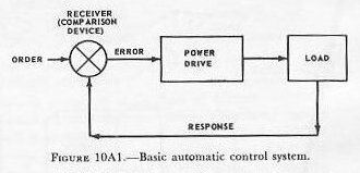
The basic technical problem incurred in driving a mount or director in response to a remote signal is divided into four general phases, as illustrated in figure 10A1.
- An order signal is received from a remote station. It is compared with the response or position of the load (mount). The result of this comparison is an error signal.
- The error signal is amplified to operate the controls of the power drive unit.
- The power drive unit drives the load in such a manner as to reduce the error signal to zero.
- In the driving of the load a response is sent back to be compared with the order signal.
B. Synchros
10B1. Introduction
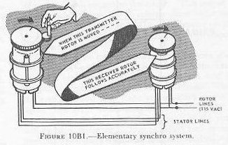
The most important unit in a modern transmission system is the synchro. Synchros of different types transmit, receive, or combine signals among stations which may be widely separated; for example, they transmit gun order signals from a computer to the automatic control equipment at a gun mount.
The simplest types of synchro units are the synchro transmitter (sometimes called synchro generator) and the synchro receiver (sometimes called synchro motor). The transmitter is a device that transmits an electrical signal corresponding to the angle of rotation of its shaft. The receiver is a device that, when it receives such a signal, causes its own shaft (if not appreciably loaded) to rotate to an angle corresponding to the signal. Thus, as figure 10B1 shows, when the transmitter shaft is rotated, the receiver shaft rotates through exactly the same angle.
10B2. How a synchro system works
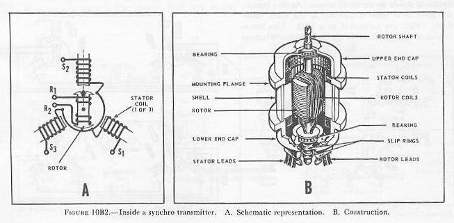
From the outside, a synchro transmitter or receiver looks much like an ordinary small motor or generator (fig. 10B1). So does the inside. See figure 10B2 (B). It has a bobbin-wound ball-bearing mounted rotor surrounded by a wound stator. The stator consists of three iron-core coils connected as in figure 10B2 (A), and terminating in three stator leads (S1, S2, S3). The two rotor leads (R1 and R2) shown in figure 10B2 (A) are connected to the rotor. See figure 10B2 (B).
The transmitter and receiver are identical in construction except that the motor has a damper (not illustrated)—a device that keeps it from “running away” when there are violent changes in its electrical input.
To understand how a synchro functions, think of it for the moment as a transformer in which the primary and secondary are wound on separate cores (fig. 10B3). When a current flows in the primary, it forms a magnetic field in its core. As the current changes and reverses (which it does constantly, being an alternating current) so does the magnetic field. The changes in the field induce current in the secondary (whose circuit is closed through a load). The currents in the secondary produce their own magnetic field. At any instant, the induced or secondary field opposes in direction that produced by the primary. Figure 10B3 shows the field at a selected instant. At some other instant the fields might be of opposite polarity, but the primary and secondary fields are always opposed, whatever the instantaneous polarity.
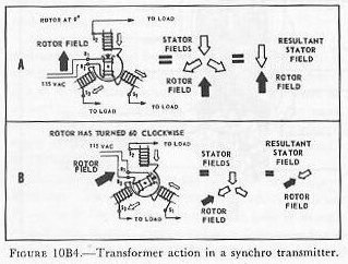
Now consider what happens in a synchro transmitter. Let 115-volt AC flow through the rotor. As shown in figure 10B4 (A), the rotor will produce a changing magnetic field. Its direction at some selected instant is shown by the black arrow. At that instant, the rotor field induces currents in the three stator fields, which are connected to a load. This transformer action produces in the three stator windings three fields (white arrows) which, when added to produce a resultant (symbolized by a large white arrow), exactly oppose the field in the (primary) rotor winding.
If the rotor is now turned, say, 60 degrees clockwise, as in figure 10B4 (B), the rotor field, shown by the black arrow, will produce in the 3 stator coils 3 fields which will again add up to a resultant directly opposed to the rotor field.
In each of the cases illustrated in figure 10B4, the rotor will induce in the stator coils currents corresponding to that position of the rotor, and to that one only. This is true for all positions of the rotor.
Now consider a synchro transmitter connected to a receiver as in figure 10B5 (A), so that the rotors are fed by the same AC line and the stator coils of the receiver load the corresponding coils of the transmitter. The currents induced in the transmitter stator flow also in the receiver, and produce the resultant stator fields shown by the white arrows. Thus the receiver rotor, which produces a magnetic field similar to that of the transmitter rotor (because it is excited by the same AC line) always, because it is free to rotate, assumes exactly the same angular position (relative to the stator) as does the transmitter rotor.
When the transmitter rotor is turned—say 30 degrees, as in figure 10B5 (B)—the resultant field produced by the stator turns too, as it did in figure 10B4; so does the receiver stator field. And the transmitter rotor, being free to follow, does. See figure 10B5 (C).
Note: In this explanation, in the interest of simplicity, the effects of the voltages induced by the receiver rotor in its stator have not been explored. However, since the transmitter does not rotate except in response to whatever drives it, the net action is substantially as described above.


10B3. Other types of synchros
The transmitter and receiver synchros described in the preceding section are only part of the synchro family. The other members are:
1. Synchro control transformer (CT). This device, like the synchro transmitter, has a wound rotor coil and three stator coils, but the internal construction is different. See figure 10B6 (A). The rotor is round instead of bobbin-shaped (to keep it from tending to line up with a magnetic field as a receiver rotor does) and is wound with finer wire to increase electrical impedance and limit the amount of current it will carry.
The synchro control transformer has 2 inputs, 1 mechanical (its rotor is driven by the mechanism or load whose position it regulates) and the other electrical (the synchro signal from the transmitter which is to control the load). See figure 10B6 (B). The electrical (synchro) 3-wire input goes into the control transformer’s stator. The stator’s field acts as the primary of the transformer; the rotor is its secondary. The output thus comes from the rotor and varies with its position with respect to the stator. This output is not a synchro signal; it is a voltage whose value and polarity with respect to the AC supply depend on the position of the control transformer’s rotor with respect to the stator.
This is how the rotor output varies with rotor position. Assume an unchanging field set up by the stator windings of a synchro control transformer, and let the rotor be turned through a full revolution. When the rotor winding is at right angles—dark arrow in figure 10B6 (A)—to the stator field—white arrow in figure 10B6 (A)—the induced voltage in the rotor will be at a minimum. This is called zero or null position. (Actually there will be small residual voltages, which can be neglected.)
As the rotor turns, the output voltage increases and reaches a maximum when the rotor winding is parallel to the stator field. As the rotor continues to turn, the output falls. At 180 degrees the output is again zero, then increases and decreases as the rotor turns, much as in the first 180 degrees of revolution. But if in the first half revolution the instantaneous polarity of rotor output was in phase with that of the stator field currents, in the second it was opposed—180 degrees out of phase.
Thus any position of the rotor with respect to the stator field will yield a characteristic output (considering both voltage and phase).
Now consider the synchro control transformer as part of a system set up to control a power unit that positions a load. Suppose that the transmitter in figure 10B6 (B) is cranked from 10 degrees position to zero. This changes the direction of the transmitter’s stator field. Since the control transformer’s stator is connected to the transmitter’s stator, the control transformer’s stator field rotates similarly. This changes the value of the output of the control transformer’s rotor from zero. Since the control transformer’s output is too small to drive a motor, it is amplified. The amplifier’s output drives a motor which positions the load. But the control transformer’s shaft is so geared to the load that, as the motor drives the load, the control transformer’s input to the amplifier falls. When the control transformer’s output is zero again, the amplifier’s output has also fallen to zero, and the motor stops. At this point, the load is in the position required by the transmitter operator.
The main advantage of a transmitter-control transformer system over a transmitter-receiver system is that friction and load weight are unimportant with a synchro control transformer, while they limit the accuracy of a synchro receiver. Any appreciable load increases a receiver’s angular error; sensitivity rather than load limits a control transformer.
The application of a synchro control transformer to a gun mount power drive is described in section 10D.

2. Synchro differential transmitter (sometimes called differential generator). The differential transmitter is a device which yields the sum or difference of two signals.
The differential transmitter’s rotor and stator each have three windings. One input to the differential transmitter is a synchro signal to the stator winding. The other input is mechanical—that is, the rotor is driven mechanically to some angle. The output from the rotor of the differential transmitter is an electrical synchro signal that represents (depending on how the system is connected) either the sum or the difference of the mechanical and electrical signal inputs. See figure 10B7. The differential transmitter is not connected to the 115-volt AC line.

3. Synchro differential receiver (sometimes called differential motor). Like the differential transmitter, the synchro differential motor yields the sum or difference of two inputs. Both inputs (fig. 10B8) are electrical synchro signals. The receiver gives the sum or difference mechanically—generally by rotating a dial. The construction of the differential receiver resembles that of the differential transmitter, except that, like the synchro receiver taken up above, it is fitted with a damper. It does not have any direct connection to the 115-volt AC line.

10B4. Summary of synchro types
The present functional classification of synchros, as described in OP 1303 (first revision in preparation at this writing), classifies all synchros into seven categories, each described by a group of letters. The classification recognizes not only the categories described in the 2 articles preceding, but also 2 broader categories—synchros designed primarily for systems producing an electrical control voltage signal, and synchros designed primarily for systems producing a mechanical movement (torque) or dial indication.
As a convenience for the student in learning about the inputs, outputs, and functions of all the types of synchros, the table below and figure 10B9 show in summary form the types of synchros discussed above. For a fully detailed description of all standard Navy types of synchros, and for complete details of the nomenclature and symbol system that also shows the size and mark and mod of standard Navy synchros, see OP 1303 and OP 1755.


10B5. Synchro dial mechanisms
A synchro receiver can be set up very simply (as shown in several figures earlier in this article) with a calibrated dial on its shaft to display information in terms of shaft rotation. It can also be set up so that it can display in addition the response of another mechanism (such as a gun mount) to the information. For example, such a set-up can show the movement of a gun mount in elevation (or train) in response to elevation (or train) gun order.
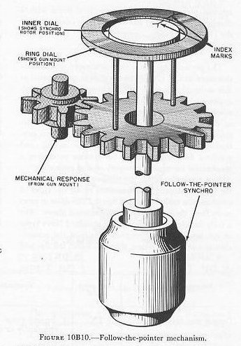
A common set-up to display such information is the follow-the-pointer mechanism, illustrated in figure 10B10. Here the synchro receiver, to which is fed a synchro signal representing gun order, drives a dial. Surrounding this dial is a ring dial geared to the mechanism (in this case, a gun mount) which is supposed to follow the transmitted signal (gun elevator or train order). A third fixed calibrated dial (not illustrated) may surround these two.
When a change in gun order occurs, the synchro rotor turns the dial. When the mount power drive or the gun pointer or trainer responds by moving the gun in accordance with the indicated order, this movement drives the response gearing, which turns the ring dial to follow the inner (synchro-driven) dial. When the two index marks match again, the gun mount is in gun order position.
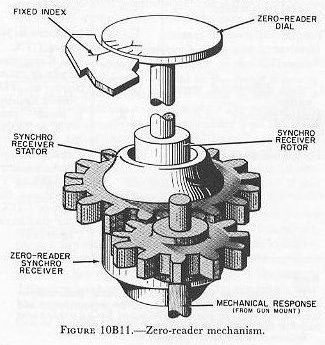
Synchros are often mounted, as in the above example, so that their stators remain fixed; however, they may also be bearing-mounted so that their stators can be mechanically rotated.
A common example of such a mounting is the zero-reader mechanism. This mechanism is used to operate a dial which displays response of a gun mount or other load to a synchro signal. The example illustrated in figure 10B11 shows a synchro receiver to which is fed a synchro signal representing gun elevation (or train) order. This turns the rotor, which turns the zero-reader dial off the fixed index mark. As the gun mount is moved automatically (by the power drive) or manually (by the gun pointer or trainer), it drives the synchro stator through gearing so that the whole synchro (including the dial) rotates toward the fixed index mark. (The rotor and stator are electrically locked together by their magnetic fields.) The zero-reader dial shows the difference between the signal and the response. When the two are equal, their difference is zero, of course. When the indexes are matched, and the dial indicates “zero,” the gun mount position corresponds to gun order position. The process of matching the indexes is called matching zero readers.
When accurate values of quantities are required, synchros are used in pairs geared to each other so that one transmits coarse readings, the other fine readings. For example, one might be used to transmit 360 degrees per revolution, the other 10 degrees per revolution. This materially increases the sensitivity and accuracy of automatic transmission. In addition, it is evident that the graduations on the fine dial can be more easily read. These are called double-speed systems.
It is possible to connect several synchro receivers to a single transmitter so that the transmitted quantity can be sent to several stations at the same time, and the values received will be synchronized at all stations.
10B6. Synchros and servos
One of the limitations of synchros is their small output torque; hence, their use is limited to positioning dials and opening and closing contacts. But often the response to the indications must be made automatic. Mechanisms which provide automatic response are called follow-ups or servo mechanisms. An electrical follow-up employs an electric servo motor to provide the additional power required.
One such follow-up, using a synchro control transformer, is shown in figure 10B6. As later articles in this chapter will show, this principle can be also used to position massive gun mounts and turrets. However, a synchro receiver can also be used for controlling a small motor in an instrument servo mechanism without requiring an amplifier. Such a set-up, in a fire control computer, is illustrated schematically in figure 10B12.
The servo motor stator has two windings, either of which may be connected in series with a phase-shifting capacitor. When one winding is in series with the capacitor, the servo motor shaft turns clockwise; when the other winding is in series with the capacitor, the rotation is counterclockwise. The servo motor is energized through the follow-up control, which consists of two sets of sensitive contacts mounted on a fixed block. A light contact arm on the synchro rotor shaft operates one or the other set of contacts, depending on which way the synchro rotor turns. The counterclockwise contacts are connected to the servo motor winding which produces counterclockwise rotation (indicated by the arrows on the end of the motor), and the clockwise contacts are connected to the other winding.
Assume that the remote synchro transmitter is sending a zero signal, and that zero bearing is set into the computer. The contact arm is in the neutral position; both sets of contacts are open; and the servo motor is motionless. As the director trains to 300, the transmitter sends a signal to the synchro receiver which rotates the contact arm clockwise far enough to close the counterclockwise contacts. This energizes the servo motor counterclockwise winding; the motor then turns the drive shaft counterclockwise, and the synchro stator rotates counterclockwise until the synchro rotor puts the contact arm in neutral position. The servo then stops, and the input to the computer is 30°. If the signal then changes to 20°, the contact arm closes the clockwise contacts, and the servo drives the synchro stator 10° to make the remaining input 20°.
Usually dials indicate the settings made by the servos. The dials may be zero readers or angle readers.
Actual follow-up mechanisms, especially in equipment of recent design, have refinements omitted in this presentation. For example, servos in which the speed or power of response is proportional to the amount of error have many advantages, such as reducing oscillation or “hunting” around the signal.
When coarse and fine synchros are used in a system, the servo mechanisms are often so constructed as to respond to a coarse error with high-speed response until it becomes a fine error, when the response is scaled down to the accuracy required for accurate synchronization with the signal.

C. Electric-Hydraulic Systems
10C1. Principles of hydraulic mechanisms
Electric-hydraulic power drives are used with all calibers of naval gun mounts from 40-mm mounts to 16-inch turrets. Their great advantage is that they provide positive control at all speeds, and in both acceleration and deceleration, of the most massive moving units—including rotating turret structures weighing millions of pounds. Complete systems are unavoidably complex, especially in the more highly automatic types of installation; but their principles of functioning can be presented relatively simply, once certain elementary facts about the behavior of liquids are known, and once certain basic hydraulic mechanisms are understood.
This article presents this fundamental background in simplified, somewhat foreshortened, form. Succeeding articles in this section explain a typical electric-hydraulic system—that for the 5"/38 twin mount.
Strictly speaking, hydraulics as a science has to do with the behavior of liquids in motion; hydrostatics has to do with the behavior of liquids at rest. This discussion will not emphasize the distinction.
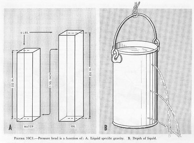
Whether at rest or in motion, all liquids are nearly incompressible, at least within the pressure ranges that are encountered in ordnance hydraulic systems. The liquid in any system is always under the pressure, called pressure head, imposed by its own weight, and this increases in proportion to depth. It varies, of course, with the specific gravity of the liquid. In water, this pressure head is 8 psi at 222 inches below the surface; in a typical oil with a lesser specific gravity, a depth of 252 inches is required to attain this pressure head.
Other pressures imposed on an enclosed hydraulic system (for example, pressure imposed by a piston on liquid in a closed cylinder) are distributed equally in all directions throughout the entire volume of the liquid. Thus a pressure imposed at one end of a long liquid-filled tube is communicated undiminished to the other end. (This applies strictly to liquids at rest; other factors modify this behavior when the liquids are in motion.)
Although, with regard to pressure transmission, all liquids are about the same, they differ radically in their resistance to flow (otherwise known as viscosity), in their lubricant effect, and in their general suitability for use in hydraulic systems. Hydraulic fluids for ordnance hydraulic systems are petroleum-based oils selected for superior lubricant quality (but they are not lubricants), low viscosity throughout a wide range of temperatures, low volatility, high stability, and compatibility with the metals of which such systems are constructed.
Hydraulic systems include some or all of the following main types of components:
- Pipe or tube lines, to conduct the fluid between components of the systems, and fittings to mate these components.
- Valves, to direct and control the flow of fluid, and to control fluid pressure. Some valves are hand operated, but most are automatic. Many, like check valves, pressure-regulating valves, and dumping valves, are hydraulically operated; others are operated by electric motors, solenoids, or synchros.
- Gages, to measure pressure, velocity, and volume of hydraulic fluid. (Ordnance hydraulic systems use mostly pressure gages.)
- Pumps, to drive the hydraulic fluid through the system. There are many types, ranging from simple rotary and reciprocating units to relatively complex axial-piston pumps whose rate and direction of output can be almost instantly varied from zero to full in either direction without varying their speed of rotation. All pumps in ordnance hydraulic systems are driven by electric motors.
- Hydraulic motors and work cylinders, whose function it is to convert the energy delivered through the hydraulic fluid to mechanical motion. Most hydraulic motors are actually somewhat modified pumps of one type or another, working in reverse.
- Pressure chambers, to protect the hydraulic system against sudden shocks and surges, and accumulators, which store a certain amount of fluid under air pressure to equalize fluid flow under sudden heavy demand in excess of the capacity of the pumps, or to complete an operating cycle in case of power failure.
- Reservoirs and tanks, to store fluid and provide for its expansion with heat.
- Gaskets to seal joints, and packing to seal openings around moving parts against leakage of fluid.
10C2. Introduction to 5"/38 twin mount train power drive
The system described in this article is a simplified version of the train drive for the 5"/38 twin mount. See figure 10C2. Refinements omitted are needed for smooth operation but do not contribute to an understanding of the principles of the system.
The main equipment consists of a variable-speed drive, an indicator-receiver-regulator, and associated auxiliary equipment.

10C3. Methods of control
This system has four methods of control: AUTO, LOCAL, HAND, and MANUAL. Selection of the type in use is made by the control-selector lever at the trainer’s station. Also located at the station is a speed-selector lever having two positions, HIGH and LOW. It has no function in automatic control, but determines the ratio between handwheel movement and follow-up operation in the other control methods.
In AUTO gun laying, the remote signal is received by a synchro receiver, is amplified hydraulically, and causes the training system to follow the signal at a maximum rate of 25 degrees per second. Figure 10C3 is a block diagram representation of this system in automatic control.
In LOCAL power control for indicator gun laying, movement of the handwheels takes the place of the remote signal entering the indicator-regulator. See figure 10C4.
In HAND control, movement of the handwheels goes directly to the A-end control unit, bypassing the indicator-regulator. See figure 10C5.
In MANUAL control, the handwheels are geared directly to the training rack, bypassing the entire power-drive unit.


10C4. Variable-speed drive (hydraulic speed gear)
The speed gear consists of a variable-displacement hydraulic pump, the output of which drives a hydraulic motor. The pump is called the A-end, and the hydraulic motor is called the B-end. The hydraulic system through the two units and the two large interconnecting pipes is referred to as the active system.
The A-end is driven at constant speed by an electric power motor through a set of planetary reduction gears. The B-end, as already mentioned, is driven by the hydraulic output of the A-end, and the mount itself is driven by the mechanical output of the B-end. See figure 10C6. By controlling the variable output of the A-end, the direction and speed of rotation of the B-end can be controlled; therefore, the direction and speed of the motion of the mount can be controlled.
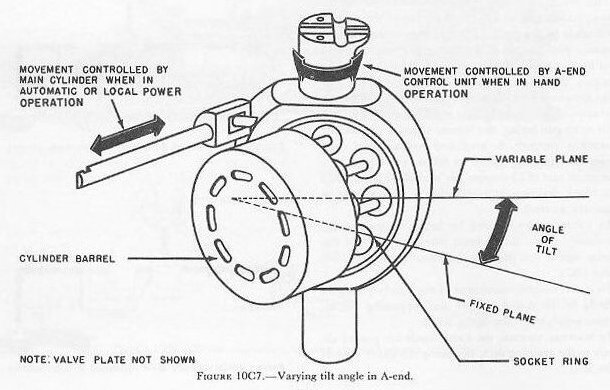
The hydraulic output of the A-end is controlled by varying the angle between the socket ring and cylinder barrel of the rotating group of the A-end. See figures 10C7, 10C8, and 10C9. This angle is called the angle of tilt and is controlled by the A-end control unit when the equipment is in HAND control. In AUTO and LOCAL power control, the angle of tilt is controlled by the position of the main piston. The position of the main piston is in turn controlled by the hydraulic follow-up system.
The cylinder barrel rotates in a fixed plane, while the socket ring rotates in a plane whose angle to the fixed plane of rotation of the cylinder barrel may be varied. The angle between these two planes is the angle of tilt. See figures 10C7 and 10C8.
The socket ring is mounted inside a large, steel, cup-like casting. This yoke is called the tilt box and does not rotate with the socket ring. Therefore, suitable thrust and radial roller bearings are provided to support the socket ring inside the tilt box. The tilt box is trunnion-mounted in large ball bearings so that the tilt box and the socket ring may be tilted anywhere within a limit of ±20 degrees from the zero tilt position. A universal joint is provided so that the socket ring may be rotated by the drive shaft as the angle of tilt varies between its limits of ±20 degrees. The same drive shaft that rotates the socket ring rotates the cylinder barrel. The cylinder barrel is keyed to the drive shaft. See figure 10C8.

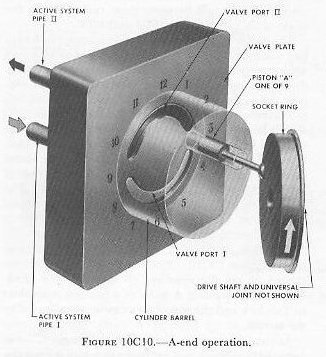
To follow piston A through a complete revolution, refer to figure 10C10. Note that the numbers are arranged as are the numbers on the dial of a clock. Then consider piston A to be at a position equivalent to 3 o’clock and the rotation clockwise as indicated by the arrows.
As rotation progresses, piston A will begin to move outward in relation to the cylinder in which it operates. The relative motion of the piston is outward until the piston is at the 9 o’clock position. The piston motion up to this point has been such as to draw oil into the cylinder in which the piston operates. The oil has entered the cylinder through valve port I and active system pipe I. Continuing the rotation from 9 o’clock to 3 o’clock it must be noted that the relative motion of the piston in its cylinder is now reversed and is inward, forcing oil out of the cylinder through valve port II and active-system pipe II.
At 9 o’clock and at 3 o’clock, where the relative motion of the piston in its cylinder reverses and where the relative motion is zero, lands are provided in the valve plate to separate port I from port II. These two points are points of commutation where the piston motion reverses from that of drawing in oil to that of pumping out oil under pressure. The two lands separate the high-pressure discharge port from the low-pressure intake port. The width of these lands must be at least as great as the diameter of the opening at the end of the cylinder. This is necessary in order to prevent a hydraulic short circuit between the low-pressure port and the high-pressure port as any one of the nine pistons of the rotating group passes over one of the lands.
The cylinder barrel bears against the valve plate at all times, and the construction of the two parts is such that leakage is reduced to a minimum.
The tilt-box trunnions are adjacent to the points designated as 6 o’clock and 12 o’clock. See figure 10C9. The tilt box rotates within limits about an axis through these two points.
It should be evident at this point that, with the tilt shown, the pumping action is such as to force oil out through port II and to draw oil in through port I. That is, the oil drawn in through port I at low pressure is pumped out through port II at high pressure. It should also be noted that if the angle of tilt is reversed the direction of flow is reversed, and that the volumetric rate of pumping depends upon the value of the angle of tilt.


The active-system piping leading from the two valve-plate ports of the A-end provides for flow of oil through to the B-end.
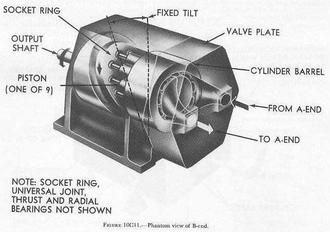
The B-end is similar in construction to the A-end, except that the tilt of the socket ring is fixed. The angle of tilt of the B-end is built into the unit and cannot be changed. See figure 10C11.
The flow of oil under pressure to the B-end will exert forces normal (at right angles) to the faces of the pistons open to the valve port receiving the oil under pressure. See figure 10C12. These forces on the piston faces will result in:
- A thrust component along the axis of rotation of the socket ring. This component does no useful work and is neutralized by a suitable thrust roller bearing.
- A turning component which will rotate the socket ring. This force component is at right angles to that described in 1. The cylinder barrel will rotate, driven by the rotation of the socket ring, through the drive shaft and universal joint. This, of course, will cause the B-end to rotate, and thereby provide the power required to drive the guns.

10C5. The A-end control unit
Control of the speed-gear output for driving the guns when the equipment is in HAND control is accomplished by action of the A-end control unit. In HAND control (see figure 10C5), the signal to the A-end control unit is transmitted mechanically through shafting and gearing from the pointer’s or trainer’s handwheels. Mechanical response is also transmitted to this unit through shafts and gears.
Within the unit is a special type of mechanical differential. Any difference between the signal and response will cause axial movement of a shaft which introduces a change in the value of the angle of tilt of the A-end tilt box.
The action of the A-end control unit is to change the angle of tilt until mechanical response and therefore gun movement is synchronized with the handwheel motion.
10C6. The indicator-receiver-regulator
The indicator-receiver-regulator (commonly called the indicator-regulator) contains all the equipment necessary for (1) receiving the order signal and the response, (2) comparing them to obtain the error signal, (3) amplifying the error signal, and (4) transmitting it to the A-end properly. It is equipped with dials which indicate the order signal and the response. The indicator-regulator is in use only when AUTO or LOCAL power gun laying is employed. (See figures 10C3 and 10C4.)
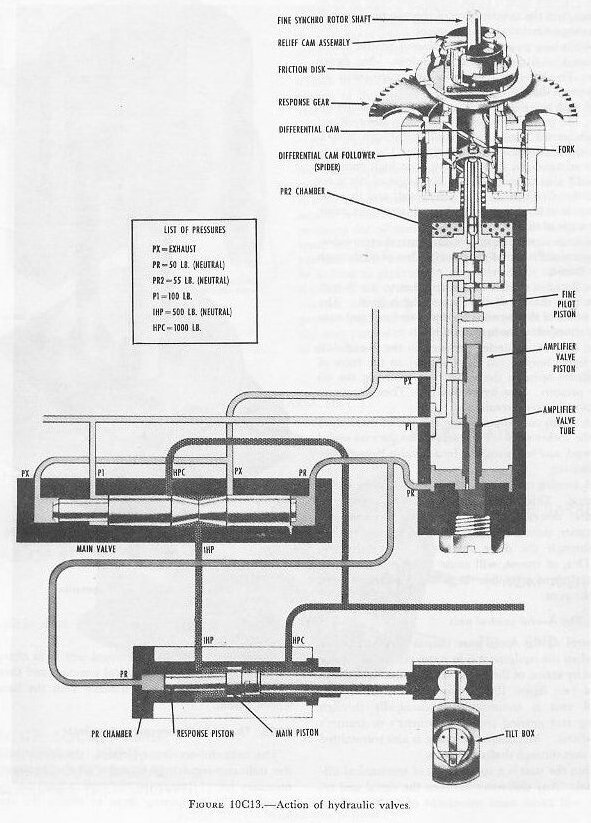
Figure 10C13 shows only the major parts of the (train) indicator-regulator. It demonstrates the control of the principal valves by movement of the fine synchro receiver. Rotation of the synchro rotor causes the fine pilot piston to move up or down. The amplifier valve piston follows the movement of the fine pilot piston. This positions the main valve, and the main valve controls the main piston, which is attached to the A-end tilt box. As the B-end drives the mount, response gearing rotates the response gear, which repositions the fine pilot piston to bring the system to rest.
In automatic control, the synchro receiver rotor receives a gun-train order from the synchro transmitter in the computer. As the rotor moves, it turns the rotating fork through the relief-cam assembly. The ends of the fork fit in slots in the differential-cam follower (spider). Since the spider is constrained to move in helical grooves in the differential cam as it is rotated, it moves up or down. Attached to the lower end of the spider is the fine pilot piston which moves with it.
Now, as the mount moves in train as a result of the above signal, gearing from the B-end output shaft turns the response gear of the differential cam. The helical grooves of the differential cam are moved while the rotating fork is preventing the spider from rotating. Thus, the spider and the fine pilot piston are raised or lowered in accordance with the signal.
On figure 10C13, we will trace one cycle of operation of the hydraulic valves shown. Assume that a signal has caused the fine piston to move up:
- Oil in chamber PR2 (at the top of the amplifier valve) escapes through the port (opened by the fine pilot piston movement) to the PX (exhaust) line. As the pressures on the top and bottom of the amplifier valve piston are no longer in balance, PR pressure on its bottom will cause the amplifier valve piston to move up, closing the port from PR2 to PX. The amplifier valve piston moves exactly the same direction and amount as the fine pilot piston, and it follows the fine pilot piston almost instantaneously.
- The main valve had been in balance, with the pressures P1 and PX working against PR. Now with the loss of volume from the PR side resulting from the rising of the amplifier valve piston, the piston of the main valve will move to the right. The IHP line to the center of the main valve is then open to the exhaust Px.
- The main piston had been in balance, with PR and IHP working against pressure HPC. With IHP opened to the exhaust, the resulting unbalance permits HPC to force the main piston to the left.
- The main piston is directly connected to the tilt box, so that its movement produces an angle of tilt.
- Now the B-end drives the mount until response gearing brings the system to rest.
It must be realized that the preceding paragraphs deal with the problem in the simplest terms. Actually, two synchro receivers are used to initiate the movement of the pilot piston. One is a coarse synchro; the other a fine at the ratio of 1:36. If the signal differs from the existing position of the mount by an angle equal to 3.8 degrees, the coarse synchro will take control to move the fine pilot piston to its maximum position and keep it there until this difference becomes less than 3.8 degrees. Then the fine synchro, through the cam, will again perform its function as described above. Also there are other valves in the system such as the acceleration, offset control, and synchronizing valves.
D. Amplidyne Follow-Up System
10D1. General
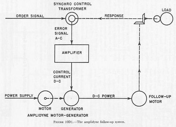
An amplidyne follow-up system in its simplest form consists of the four units shown in figure 10D1:
- The synchro control transformer.
- The amplifier.
- The amplidyne motor-generator.
- The follow-up DC motor.
The synchro control transformer receives the order signal which indicates electrically what the position of the load should be. The rotor of the synchro control transformer is turned by the response shaft, which is geared to the load and so indicates what the position of the load actually is. The synchro compares the actual load position with the ordered position; and, if the two do not agree, it generates an alternating-current signal which is transmitted to the amplifier. The angular difference between the two positions is called the error, and the signal to the amplifier is the error signal. The error signal indicates by its electrical characteristics the size and direction of the error. If no error exists, the system is said to be in correspondence and the error signal is zero.
The amplifier receives the alternating-current error signal, amplifies it, and converts it into direct current suitable to energize the field windings of the amplidyne generator.
The amplidyne generator supplies direct current to operate the follow-up motor. The direction of rotation of the motor depends on the polarity of the output of the amplidyne generator, which in turn depends on the direction of the error as indicated by the error signal. As a result, the motor moves the load in the proper direction to reduce the error.
The amplidyne generator is a power amplifier on a large scale. Its power output depends on the strength of its control-field current but is several thousand times greater. The additional power is supplied by the motor which drives the amplidyne generator. The strength of the control-field current from the amplifier depends on the size of the error as indicated by the error signal. The power applied to the follow-up motor, therefore, is greater for a large error than for a small one.
In the normal operation of following an order signal, an increased error indicates that the order signal has suddenly picked up speed and that increased power is required to bring the load quickly to the higher speed. In response to an increased error, the amplidyne generator promptly supplies the necessary added power. If the order signal suddenly slows down, the load may overrun the signal and reverse the direction of the error. As a result, the polarity of the amplidyne output is reversed; the motor tries to run in the reverse direction, and so applies a retarding force to the load.
When the order signal moves at a uniform speed, the motor must supply only enough power to overcome the friction in the system. The power output of the amplidyne is then much less than when the speed is increasing or decreasing, and the error will be correspondingly smaller.
Because of the immense power amplification available in the amplidyne generator and amplifier, an extremely small error signal supplies enough power to control the mount. In following the usual gun-train or gun-elevation order, the errors should not be more than a few minutes of arc under the most adverse conditions.
10D2. Synchro control transformer
The functioning of a synchro control transformer was described earlier in this chapter. As in the system described in article 10B3, the synchro control transformer’s output in an amplidyne system produces an AC output signal which depends on the position of the rotor with respect to the stator’s magnetic field. The stator receives a gun-order synchro signal from a synchro transmitter, and the synchro control transformer’s rotor is driven by the gun mount. As the gun mount is driven toward gun-order position by the amplidyne power drive, the control transformer’s rotor approaches the null position. At null, the gun mount is in gun-order position.
Because of the sensitivity of the system, the synchro control transformer’s output very closely controls the operation of the power drive, increasing acceleration of the mount’s movement as the rotor signal increases, and minimizing overshooting.
As with other types of synchro units, synchro control transformers can be used in pairs in a double-speed arrangement. Identical synchros are used, but they are geared at 36:1. Both synchros are connected to the input of an electronic amplifier, but a relay, switching circuit, or electrical network automatically selects the output of either the coarse or the fine synchro. The coarse synchro control transformer’s signal is switched to the amplifier input when the gun mount is more than about 3° out of synchronism. As the gun mount approaches synchronism with the gun-order signal, the fine synchro signal automatically switches into the circuit to furnish the controlling input to the amplifier and continue gun mount movement until it is fully matched with gun order.
10D3. Amplifier
The function of the amplifier is to supply two control-field currents for the amplidyne generator. In following an order signal in automatic control, these currents must be varied in accordance with changes in the error signal. When the error signal is zero, the two control currents should be equal. When the error signal calls for movement of the mount in one direction, one control current must increase and the other must decrease. When the mount is to move in the opposite direction, the unbalance in the control currents must be reversed.
The amplifier has two stages. The first stage is primarily a rectifier stage in which two direct currents are produced whose magnitudes are controlled by the error signal. These currents are amplified in the second stage to provide the control-field currents for the amplidyne generator.
10D4. Amplidyne generator
The construction and operation of the amplidyne generator can best be understood by following through the steps necessary to convert an ordinary direct current generator into an amplidyne generator.
When a coil of wire is rotated in a magnetic field, voltages are induced in the coil, and, if the ends of the coil are connected together, these voltages cause electric currents to flow in the coil. This is the basic principle of a generator.
The principal parts of a generator are the stator, or stationary part, and the armature, or rotating part. In a common form of generator, a coil of wire is wound on a part of the stator and is supplied with a small exciting current which magnetizes the iron in the stator and armature to provide the necessary magnetic fields. The armature carries other coils which are rotated in the magnetic field as the armature is turned. As a result, voltages are induced in the armature coils.
The ends of the armature coils in a DC generator are connected to copper bars on a commutator which rotates with the armature. The voltages induced in the coils are taken off by stationary carbon brushes engaging the commutator as it turns. If the brushes are connected together through an external circuit, current will flow in the circuit and through the armature coils.
The connections to the commutators are such that the maximum voltage appears across two points on opposite sides of the commutator. The positions of these points depend on the direction of the magnetic field and do not change as the commutator rotates. The brushes are located at or near these points to take advantage of the maximum voltage.
In figure 10D2, the upper view represents an ordinary direct-current generator such as the one just described. The inner circle is the commutator, with brushes at top and bottom. The next circle represents the armature, and the outer structure is the stator with a coil carrying the exciting current wound on its pole piece. Other conditions being equal, the power output of the generator will be proportional to the power input to the excitation winding, within the limits of normal operation. This generator is assumed to be a 10-kw machine (10,000 watts output), and the excitation required is about 100 watts. The amplification, therefore, is 100 to 1.
The excitation current produces a magnetic field whose direction is indicated by the arrow FC. It is this magnetic field which induces the 100 volts which appears across the brushes. At the same time, the 100-amp load current flowing in the armature coils creates another magnetic field FS at right angles to FC. It has about the same strength as the field FC. This second magnetic field, called armature reaction, does no useful work in the ordinary generator and is, in fact, a source of trouble.
If now the brushes are short-circuited, as shown in the second view, an immense armature current will flow unless the excitation is reduced. If the excitation is cut down to about 1 watt, FC is reduced accordingly, and the normal full-load current of 100 amperes flows through the short-circuit path. This current produces the same armature reaction FS as before.
The armature reaction FS induces a voltage in the armature in the same manner as flux FC but this voltage appears on the commutator at 90 degrees from the voltage induced by FC. A voltmeter connected to points on the commutator, as shown in the second view, will indicate approximately full-load voltage.
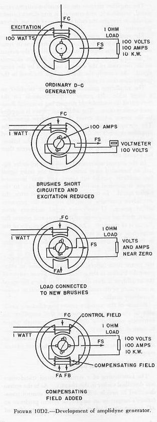
In the next view, new brushes have been added to points 90 degrees from the original brushes, and the original load of 1 ohm has been connected between them. The high voltage formerly existing between these points has almost disappeared. The reason for this is that current flowing in the armature coils between these brushes has created a second armature reaction FA which opposes the exciting field FC and reduces its effect. The decrease in the effect of FC reduces FS and consequently reduces the voltage across the new brushes.
The lower view shows the last modification necessary to produce an amplidyne generator. The armature current from the new brushes has been taken through a compensating field winding and creates a magnetic field FB opposed to FA. This field may be adjusted to balance out FA and thus restore the full effect of the exciting field FC. FS is restored to normal, and full-load current may be drawn from the new brushes. Since both FA and FB depend on armature current, they will always be approximately balanced and the output voltage is nearly independent of the armature current. Full-load output has been obtained with only 1-watt excitation instead of 100. The amplification is 10,000 to 1 instead of 100 to 1.
Other refinements are necessary to produce the fast, stable operation necessary in a follow-up system, but the machine shown in the lower view of figure 10D2 is the basic form of all amplidyne generators. In the equipment now in use, excitation is supplied to two control windings which are oppositely wound. The direction of the magnetic field FC and the polarity of the output of the generator depend upon which winding receives the stronger current. Thus, the direction of rotation of the follow-up motor, which receives its power supply from the amplidyne generator, can be controlled at will by supplying the stronger current to one or the other of the control fields. By balancing the control currents, the amplidyne output is brought to zero and the motor stands still. The difference between the two control currents determines the amount of power supplied to the motor.
10D5. 5"/54 amplidyne train drive
An example of amplidyne power drives in the Navy is the Train Power Drive Mark 14 on the 5"/54 single mount.
The main units in this system at the mount are (1) gun train indicator-regulator, (2) 40-hp train motor, (3) brake unit, (4) train-selector switch, (5) master switch, and (6) shifting clutch; those located in the amplidyne control room below deck are (7) train amplidyne motor-generator and (8) amplifier unit. See figure 10D3.
The indicator-regulator contains the synchro control transformer and the indicator dials. The brake unit is a safety mechanism which locks the drive and holds the mount stationary if power supply fails during power operation. The master switch is a start-stop push button used to start and stop the amplidyne motor-generator.
The shifting lever has two main positions, MANUAL and POWER. A middle position of STOP acts as a safety feature in shifting the mount between power and manual.
The selector switch has four positions: AUTO, LOCAL HIGH, LOCAL MEDIUM, and LOCAL LOW. It is used to select any of these four means of power operation of the mount.

E. Other Types
10E1. Thyratron system
Thyratron systems are found on stable elements and stable verticals which require a simple and accurate low-power automatic control system. In this system the electrical (AC) signal is amplified by electronic tubes. The amplified signal is then changed to DC by 1 of 2 half-wave rectifier tubes. A signal in 1 direction utilizes 1 rectifier tube, while a signal in the other direction utilizes the other rectifier tube. The DC output of the rectifier tubes is led to a DC motor, the direction of rotation of which depends upon which of the rectifier tubes furnishes the voltage. This DC motor furnishes the working power for the system.
10E2. York Safe and Lock Company drive
This drive, used extensively as the train and elevation units on 40-mm mounts, is an electric-hydraulic drive using both electronic and hydraulic amplification. Figure 10E1 is a simplified schematic drawing of the drive.
The main parts of this system consist of an electric power motor, a hydraulic A-end pump and B-end motor, and a receiver-regulator control system. The electric motor drives the A-end pump. Fluid from the A-end drives the B-end in the proper direction and amount. The B-end is directly geared to the mount to drive it in train (elevation). The receiver-regulator controls the position of the tilt box of the A-end in the following manner:
The receiver-regulator has a control transformer which sends an electrical error signal to an electronic amplifier. The amplified signal drives a stroke motor which controls a hydraulic pilot valve. This pilot valve positions the booster piston directly connected to the A-end tilt box, thereby providing the necessary control of the mount. As the stroke motor rotates, it drives the stroke generator, which sends a pre-response signal back to the amplifier, thus smoothing out the operation of the system.
This mount is equipped with a three-position selector lever whose settings are: MANUAL, LOCAL, and AUTO. In MANUAL control the pointer’s and trainer’s handwheels drive the mount and the power motors are not energized; however, the lag meter may be used to match a signal from the director. The lag meter is a voltmeter indication of the error signal. In LOCAL power control, the pointer controls the mount in train and elevation through use of the handle control (joy stick). In AUTO, the mount is positioned by the power drives using remote signals from a director.

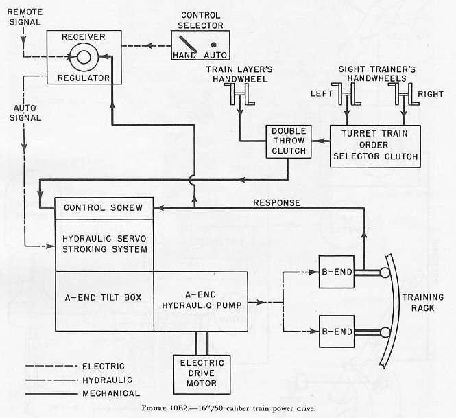
10E3. 16"/50 turret train drive
The automatic control equipment used to train the 16"/50 caliber turret is an electric-hydraulic drive designed by the General Electric Company. See figure 10E2.
The main units of this system are the electric drive motor, the variable-speed gear consisting of 1 A-end and 2 B-ends, a servo stroking system, and a receiver-regulator.
Turret train movement is controlled by positioning the A-end tilt box. Such tilt-box movement is performed by a servo stroking cylinder and piston under hydraulic pressure from a control pressure pump. Opening of servo pressure to the stroking cylinder is controlled by two methods: HAND and AUTO.
In HAND control, movement of the trainer’s handwheels rotates a nut on the control screw, causing the screw to move axially within the nut. This movement of the screw through linkages and valves controls the flow of fluid into the servo cylinder, moving the servo piston. The servo piston, being directly connected to the A-end tilt box, tilts it the amount ordered. As the turret trains, response turns the control screw, moving it axially and thereby repositioning the tilt box back to its neutral position. Handwheel motion may come from the train layer’s station or from either the left or the right sight trainer’s stations, depending on the positions of the clutches.
In AUTO control, the remote signal is received at the receiver-regulator by a synchro. The rotor of the synchro positions a small hydraulic valve. This signal is amplified hydraulically and controls the flow of fluid into the servo cylinder. This positions the servo piston and, hence, the A-end tilt box. Response, as the turret trains, rotates the stator of the synchro and returns the synchro rotor and the A-end tilt box to neutral.
10E4. Fuze-setting drives
An all-electric type of drive is used on automatic fuze setters. This drive may be considered nothing more than a two-stage servo-motor drive. Movement of the synchro receiver rotor, in response to the remote signal, closes contacts to a 115-volt AC pilot motor. Rotation of this pilot motor shaft closes silver contacts which sends 115-volt alternating current to the power motor, and causes it to drive the load in the proper direction. Rotation of this pilot-motor shaft also rotates the synchro receiver stator, returning it to neutral and opening the first set of contacts. Response from the load drives back to the power-control head of the pilot motor, opening the second set of silver contacts and stopping the power motor when the load is positioned in response to the original signal.
F. Shipboard Tests of Automatic Control Equipment
10F1. General
Frequently, errors made by automatic control equipment in following a remote signal are obvious and may be readily determined without special apparatus. A mount matching a fixed signal may be in error by a constant amount such as 10 or 120 degrees. This type of error may be only a mistake in wiring, which is easily corrected. In certain types of drives, such as 40-mm, matching 180 degrees out may occur because the error voltage for 180 degrees error is zero, since the coarse synchro is 2-speed (i.e., 1 revolution of the synchro causes 180° revolution of the mount). Excessive oscillation of the mount or sluggishness in following a signal indicates that the drive needs adjustment. In order to determine whether a drive is following a signal accurately, instruments such as the dummy director with its accompanying error recorder are used. See the next article.
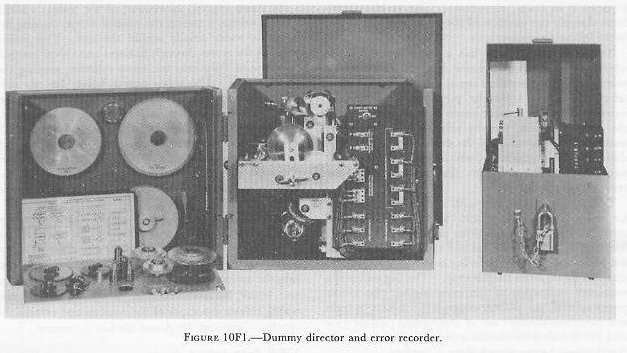
10F2. Dummy-director tests
Using a dummy director and error recorder, the dynamic accuracy (error in following a remote signal) of automatic control equipment may be determined.
The dummy director is an instrument which transmits an electrical order signal to the control equipment of the unit under test. The motion introduced may be either constant or simple harmonic.
The error recorder (spark recorder) measures and makes a permanent record of the error on a strip of paper. Figure 10F2 shows sample recordings. If no error exists, the recording shows a straight horizontal line. The amount of variation of the plot from the zero error line, therefore, is a measure of the error in minutes.
Such tests are made whenever equipment does not seem to be functioning properly, as well as periodically each quarter and during shipyard overhaul.
