
A. General
9A1. General
Automatic guns are case guns in which part of the energy of explosion is used to eject the empty cases and to activate a device which reloads and continues to fire the gun as long as the trigger is operated and the ammunition supply is maintained. All short-range (3,000 yards) AA guns aboard ship are automatic weapons.
The short-range automatic weapons used by the Navy include 20-mm and 40-mm guns, both of which were used in destroying the enemy's air power in World War II.
The United States Navy's medium-range (8,000 yards) AA weapon is the semiautomatic 3"/50 gun, with a separately powered automatic loader making it in effect an automatic gun. This weapon has been developed from the old semiautomatic 3-inch gun which was still used in World War II.
This chapter takes up the 20-mm aircraft gun, the 40-mm AA gun, and the new 3"/50 gun, as representative of present aircraft and AA machine guns. It does not take up the 20-mm AA gun or the old 3"/50 without automatic loader.
B. The 20-mm Aircraft Gun
9B1. The General Problem of Aviation Gunnery
Because aircraft speeds are high and constantly tend to become higher, actual firing time in any attack is limited to seconds. For this reason it is essential that rate of fire be rapid, so that there is reasonable probability of scoring enough hits to do effective damage. High projectile velocity is also desirable, to reduce time of flight and thereby minimize the effect of many variables which tend to detract from accuracy. It must also be remembered that performance of the airplane itself is a factor in the effective employment of the plane's guns.
Recognition of targets is one of the most critical items in air combat, because it is the key to making initial estimates of range, speed, and mission. A common error in aerial gunnery is to open fire before the target comes within range, and to continue fire when the target is beyond effective range.
In fact, the general problems of aircraft gunnery can be reduced to questions of who, where, and when. “Who” refers to the problem of whether a potential target is friend or foe, and if foe, what the type of plane may be. “Where” is the problem of target location relative to the gun, which in modern installations may be solved or largely solved by automatic means.
“When” is the problem of when to open and cease fire to provide maximum probability of obtaining hits, yet maintain necessary conservation of a limited ammunition supply.
9B2. Types of Aircraft Guns and Installations
Aircraft guns incorporate certain modifications of conventional gun structures to reduce weight and length, and generally to make them adaptable to aircraft installation. Guns as small as caliber .30 machine guns, and as large as 75-mm guns, have been installed in military planes. The aviation gun in current Navy use is the 20-mm automatic gun, but the caliber .50 machine gun was the one most extensively used in Navy planes throughout World War II. However, the latter weapon seems destined to have little potential significance in future aircraft installations.
Aircraft guns may be installed on either fixed or free mounts. Fixed guns are rigidly attached in the forward part of the plane, including leading wing edges, and may be trained or elevated only by maneuvering the plane. They are, of course, forward-firing guns. Free mounts, on the other hand, provide for train and elevation in limited arcs.
The British first used airplane turrets mounting flexible guns in battle during World War II. The modern aircraft turret is a self-contained mechanized unit, consisting of an enclosure housing the gunner, guns, ammunition, power drives in train and elevation, armor plate, and other accessories. Such an installation provides many advantages: the angle of fire is increased; movement of guns in elevation and train against the force of the slipstream is facilitated; larger guns can be utilized more readily; the gunner is protected; and, in general, a more adequate defense can be realized in the case of larger, slower aircraft. In addition, a fire control system may be installed to provide local and remote control.

9B3. Development of the 20-mm Gun M3
During the interim between World War I and World War II, both the Germans and the Japanese developed 20-mm guns for aircraft installation, and during World War II the Germans installed as many as six of these guns in some planes. Our own development of a 20-mm gun was initiated in 1937, and speeded up when the European conflict began.
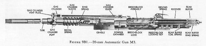
Since its inception this gun has undergone two major changes, each incorporating some improvement in design and operating characteristics. The end product of this technological advance is the 20-mm Aircraft Gun M3. Figures 9B1 and 9B2 show this gun.
9B4. General Description
The 20-mm Aircraft Automatic Gun M3 is an air-cooled weapon weighing approximately 100 pounds, and is capable of firing up to 800 rounds of ammunition per minute at an initial velocity of 2,730 feet per second.
Operating with the gun is a feed mechanism mounted on top of the gun proper. Rounds of ammunition are fed into the gun from a disintegrating link belt. A charger retracts the breechblock initially and cocks the gun, or can remove a round from the chamber. Firing is done by an electric trigger, which fires the 20-mm Automatic Gun M3 by remote control. Each of these units will be discussed below.
9B5. Principles of Functioning
Power to keep the gun operating automatically comes from the energy released each time a round is fired. This energy is utilized in three ways:
- When the round is fired, some of the ammunition propellent gas goes through a small hole drilled in the gun barrel to act on the gun components and unlock the breech block. This is called gas operation.
- The expanding gas remaining in the gun barrel pushes the breech locking and closing components to the rear. This is called blowback.
- Firing the gun causes some of the gun components to recoil. The energy of recoil compresses springs of some of the gun components. The expansion of these springs causes these components to counterrecoil and return the gun to battery. Recoil and counterrecoil activate the feed mechanism which supplies ammunition to the gun.
Since the 20-mm M3 gun utilizes all these sources of power, it is classified as a combination gas-operated, blowback, and recoil weapon.
The functioning of the main parts of the gun in the entire automatic action is described under the following heads:
- Recoil mechanism.
- Receiver.
- Breechblock.
- Driving-spring assembly.
- Gas mechanism.
9B6. Recoil Mechanism
The function of the recoil mechanism is to cushion the impact of recoil and return the gun to battery. The recoil mechanism consists of a recoil spring and a recoil housing assembly.
Recoil spring. The recoil spring is a heavy, flat, helical (or coil) spring which surrounds a portion of the gun barrel slightly forward of the chamber. The front end of the recoil spring seats against a bracket which is directly attached to the gun barrel and recoils with it. The after end of the recoil spring rests against the recoil housing assembly, a nonrecoiling part.
Recoil housing assembly. The recoil housing assembly consists of two main parts: a hollow tube, or sleeve, and a separate spring called the ring spring, which fits inside the sleeve. The sleeve is a cylindrical steel tube that surrounds the gun barrel abaft the recoil spring. It is secured to the stationary mounting assembly of the gun and does not recoil.
As the gun recoils, the gun barrel moves rearward, attempting to carry the recoil spring with it. The recoil spring bears against the ring spring inside the sleeve of the recoil housing assembly. The stationary sleeve forces both springs to compress, stopping the recoil movement. Recovery of the springs initiates counterrecoil and returns the gun to the battery position.
9B7. Receiver
The receiver is the component of the gun assembly that mounts the barrel and houses the breechblock and driving-spring assembly. It consists of three main components: the receiver body, the breechblock-locking key, and the receiver slides.
Receiver body. The receiver body is a hollow rectangle, partially open at the top and bottom and fully open at the rear. A large opening in the front end of the receiver body is threaded to receive the gun barrel. Since the gun barrel is directly attached to the receiver, the receiver is a recoiling part.
Breechblock-locking key. In approximately the midpoint of the receiver, near the bottom, a solid rectangular breechblock-locking key passes through slots on the sides of the receiver body. This key keeps the breechblock, which slides back and forth in the receiver, locked up tight against the chamber during firing. Its action will be described later in more detail.
Receiver slides. The two receiver slides are metal strips bolted inside the front of the receiver body, one on each side. They support the breechblock when it is in the front of the receiver body, and aid in locking the breechblock in firing position. Cam surfaces at the rear of the slides engage corresponding cam surfaces on the breechblock lock (a hinged arm) of the breechblock mechanism as it moves forward in the receiver. The resulting action forces the lock downward into a notch in the breechblock-locking key and locks the breechblock in firing position.

9B8. Breechblock
The breechblock moves forward and backward inside the receiver body. On the forward movement it takes the ammunition cartridge from the mouth of the feed mechanism, carries it into the chamber, and fires the round. On its return stroke, the breechblock carries the empty cartridge case to the ejector. Figure 9B3 is a sectional view of the breechblock.
The breechblock consists of the bolt, the breechblock lock, two breechblock slides, a firing pin, and an extractor. See figure 9B3.
Bolt. The bolt is the main component of the breechblock. It helps carry the cartridge to the gun-barrel chamber and closes the breech end of the barrel. It also houses the firing pin and supports the breechblock slides, the extractor, and the breechblock lock.
The firing pin and driving spring are inside the longitudinal tunnel of the bolt. The tip of the firing pin protrudes through a small tapered hole in the front of the bolt. The bolt's front face is recessed to accommodate the base of the cartridge case.
Flanges along the lower edges of the bolt guide the breechblock slides. The bottom of the bolt is recessed at the rear to receive the breechblock lock, and at the front to accommodate the extractor. The extractor is attached to the bolt by the extractor pin and a cylindrical strut-type spring which forces the forward end of the extractor toward the face of the bolt.
Breechblock lock. The breechblock lock seats on the breechblock-locking key. It locks the breechblock in battery while the round is fired.
The breechblock lock is a flat plate with cams projecting from each side of its top surface. When the breechblock moves forward, these cams engage the receiver slides and force the breechblock lock downward against the breechblock-locking key. The rounded forward edge of the breechblock lock fits into a mating recess in the breechblock bolt. This arrangement provides a hinge action between the lock and the bolt. The protruding shoulders on top of the lock move up into the notched section of the breechblock slides when the slides are retracted.
Breechblock slides. Two breechblock slides serve to guide and support the bolt in the receiver. These slides are shorter than the bolt, and slide forward and backward on the flanges along the lower edge of the bolt.
The two slides, one on each side of the bolt, are keyed together by the slide key, a flat, rectangular piece of metal with rounded edges, which extends through a slot in the bolt. This slot is elongated to allow the slide key to move forward and backward during the locking and unlocking action of the breechblock. The slide key also mates with a recess in the firing pin, so that the breechblock slides and firing pin operate together.
The bottom edges, near the rear of the breechblock slides, have notched recesses cut in them to accommodate the raised shoulders of the breechblock lock when the breechblock is unlocked. It will be remembered that the breechblock lock, hinged to the bolt, is cammed down by the receiver slides and engages with the breechblock-locking key as the breechblock moves forward just prior to firing. At this time the breechblock is in its full forward position in the receiver, and the breech end of the gun barrel is closed and locked. This is the firing position.
The breechblock lock cannot move back up into the notched recesses in the breechblock slides, because the slides continue to travel forward slightly after the lock is cammed down. The rear ends of the breechblock slides, abaft the notched recess, rest on top of the raised shoulders of the breechblock lock and prevent it from rising.
When the breechblock is unlocked by the gas mechanism after firing, the breechblock slides are pushed backward by push rods, which also compress springs inside the slides. See figure 9B4. The forward inner notched surface of the slides catches the raised shoulders of the breechblock lock and forces it up and free from the breechblock-locking key. The breechblock lock moves back up into the recess in the slides and prevents the slides from moving with respect to the bolt. The slides, however, have stored energy in the compressed springs located inside them. When the breechblock lock is cammed down, freeing the slides to move, the springs expand and push the slides forward.
Firing pin. The firing pin strikes the round in the chamber of the gun barrel and fires the round. The firing pin is cylindrical, with a tapered tip in front and a machined slot approximately in the center of the body. The slot allows the firing pin to ride on the slide key which extends between the two breechblock slides. As the breechblock moves to battery position, the breechblock slides and slide key carry the firing pin forward, causing its tip to protrude from the breechblock bolt and fire the round. After firing, the breechblock slides and slide key move rearward and retract the firing pin.
Extractor. The extractor grips the round as it enters the chamber, holds the round during firing, and draws the empty case rearward as the breechblock is blown back by the expanding gases after firing. Ejector prongs fastened to a nonrecoiling part of the gun assembly strike the top of the cartridge case as it moves rearward. The extractor and empty case are pivoted downward, and the case drops through a hole in the bottom of the receiver and out of the gun. The extractor spring forces the extractor upward to the position where it grips the next round.

9B9. Driving-Spring Assembly
When initial recoil movement begins, the barrel, receiver, and breechblock all move rearward together. Shortly after recoil begins, however, the breechblock is unlocked from the receiver. The expanding gases in the chamber, acting against the face of the breechblock, blow it back faster than the receiver and barrel are recoiling. The recoil mechanism, discussed earlier, absorbs the force of recoil and initiates counterrecoil.
The receiver will not carry the breechblock forward with it in counterrecoil, since the two are not locked together as at the moment of firing. It is the function of the driving-spring assembly to make the breechblock counterrecoil and return to battery position.
The main parts of the driving-spring assembly are the driving-spring plunger and the driving spring.
Driving-spring plunger. The forward end of the driving-spring plunger is attached to the base of the firing pin. The after end is attached to the rearmost component of the gun assembly, the rear buffer, which in turn is attached to the rear of the receiver. The plunger telescopes as the breechblock is blown back.
Driving spring. The driving spring surrounds the plunger and is compressed as the breechblock moves to the rear. It is the recovery of the driving spring that drives the breechblock forward to strip a round out of the feed mechanism and chamber it ready to be fired by the firing pin.
9B10. Gas Mechanism
The gas mechanism unlocks the breechblock and retracts the firing pin when the gun has fired. The gas mechanism consists of a cylinder which mounts on top of the gun, covering a small hole drilled in the top of the barrel; a piston and rod which move rearward in the cylinder against spring pressure; and two push rods which are forced rearward by an extension of the piston rod, called the yoke (fig. 9B4).
As the gun is fired, the projectile moves forward, uncovering the small hole, or port, in the top of the barrel. Some of the expanding propellent gas escapes through the port into the cylinder, where it exerts pressure on a piston and rod, forcing the rod rearward against spring pressure. The yoke on the piston rod pushes the two push rods, which are free to move back and forth in longitudinal holes drilled in the front of the receiver body. In turn, the two push rods, when forced rearward by the yoke, force the breechblock slides back, retracting the firing pin and unlocking the breechblock.
The propellent gases, still inside the barrel, force the breechblock rapidly to the rear. (This is blowback.) As the gas pressure lessens in the gun barrel and the gas cylinder, spring pressure in the cylinder gradually forces the piston rod and yoke forward to the position where they are ready for another cycle. The push rods slide forward freely when struck by the counterrecoiling breechblock slides.
9B11. Cyclic Action
In an automatic gun like the 20-mm Aircraft Automatic Gun M3, the firing of a round furnishes the energy to carry on the cyclic functioning of the gun to fire succeeding rounds. The sequence of cyclic actions is:
- Gun fires and recoils.
- Breechblock unlocks.
- Breech opens and fired case is ejected.
- Gun counterrecoils and driving spring drives breechblock forward (picking up a new round).
- Breechblock locks.
- Gun fires and recoils.
9B12. Gun Fires and Recoils
When the round is fired, the gun barrel, receiver, and breechblock recoil. The gun barrel carries rearward the recoil spring which surrounds it. The recoil spring contacts the ring spring inside the stationary sleeve of the recoil housing assembly, compressing both springs and stopping recoil movement.
9B13. Breechblock Unlocks
At the moment of firing, the breechblock is held against the breech of the gun barrel by the breechblock lock resting against the breechblock-locking key. The breechblock lock slides prevent the breechblock lock from disengaging until after firing.
The action of the gas mechanism unlocks the breech as shown in figure 9B4. Propellent gases enter the gas cylinder through the small hole in the gun barrel. Gas pressure forces the piston rod and yoke aft. The yoke, through the two push rods, forces the breechblock slides rearward. The breechblock slides are connected by the breechblock-slide key, which actuates the firing pin. The firing pin is notched to fit over the breechblock-slide key. Therefore, as the breechblock slides move rearward, the breechblock-slide key retracts the firing pin. The notched sections at the rear of the breechblock slides engage the protruding shoulders of the breechblock lock, forcing the lock clear of the breechblock-locking key, and unlocking the breechblock.
9B14. Breech Opens and Fired Case Is Ejected
After unlocking, blowback starts the breechblock to the rear. As gas pressure in the gun barrel drops, spring action in the gas cylinder returns the gas mechanism components to their original position. The breechblock and extractor move backward until the tip of the fired case strikes the stationary ejector prongs, pivoting the empty case out of a hole in the bottom of the receiver and out of the gun.
9B15. Gun Counterrecoils and Driving Spring Drives Breechblock Forward
The recoil spring and ring spring, which were compressed during recoil, now expand and start the receiver and gun barrel forward in counterrecoil.
The breechblock, when it was blown back in the receiver, compressed the driving spring in the bolt. Recovery of the driving spring sends the breechblock forward toward firing position, where it picks up a new round of ammunition from the feed mechanism.
9B16. Breechblock Locks
As the breechblock moves forward in the receiver, projecting cams on the breechblock lock engage camming surfaces on the receiver slides, forcing the lock to rotate downward. The breechblock lock seats against the breechblock-locking key in the receiver, and is held by the rear lower surface of the breechblock slides. Simultaneously, the breechblock bolt reaches the end of its forward motion and chambers the cartridge. The slide springs, combined with the momentum of the driving spring, cause the breechblock slides and breechblock slide key to continue forward after the bolt has stopped.
9B17. Gun Fires and Recoils
The firing pin is carried forward by the breechblock-slide key, and by the expanding driving spring. The firing pin strikes the cartridge primer and fires the round. This cycle repeats until the trigger is released or the ammunition is expended.
9B18. Feed Mechanism
The feed mechanism used with the 20-mm Aircraft Automatic Gun M3 is designated the AN-M2 feed mechanism. It is designed to feed up to 800 rounds of ammunition per minute into the gun. The linear movement of gun components in recoil and counterrecoil is transformed to rotary motion by mechanical means in the feed mechanism. This rotary motion winds coil springs which drive a set of starwheels. The starwheels are 9-toothed sprockets contoured to fit between the cartridge cases in the ammunition belt. As the starwheel housing rotates, the two starwheels engage the incoming rounds, drawing them into the feed mechanism. Once inside, stripper cams strip off the detachable links which hold the rounds together in belts. The cartridge is then aligned with the mouth of the feed mechanism. The extractor grips it and rams it into the gun chamber.
9B19. Charger
A charger is used to retract the breechblock and cock the gun, or to remove a round from the chamber. A lug on the breechblock slide extends through a long slot in the receiver. This lug is engaged by the charger, which draws the entire breechblock assembly to the rear until it reaches the cocked position. The breechblock is held in this position by the trigger mechanism. Chargers may be either manually, hydraulically, or pneumatically operated.
9B20. Electric Trigger
The trigger in the pilot's compartment and the mechanism which actuates firing at the gun are connected electrically. The mechanism that holds the breechblock in the rear of the receiver and prevents firing is the sear. The sear mechanism is fastened to the underside of the receiver. The sear itself is a hooked arm which engages with a recess in the bottom of the breechblock lock, preventing it from moving forward. The other main part of the sear mechanism is a solenoid assembly. Pressing the trigger causes the solenoid assembly to draw the sear out of the path of the breechblock. When the circuit is opened, a spring forces the sear upward again, where it engages the breechblock lock.
C. The 40-mm Guns and Mounts
9C1. General
The 40-mm gun is a recoil-operated, heavy machine gun designed primarily for AA fire. Its distinctive features include (1) a vertical sliding-wedge breech mechanism, (2) a hand-fed automatic loader, (3) a spring-operated rammer, and (4) a trigger mechanism that controls the rammer operation only.
Once put in operation and the ramming cycle started, this gun loads and fires without further attention. It can be operated in either fully automatic or single fire. The maximum cyclic rate of automatic fire is about 160 rounds per minute.
For naval use, these guns are usually water-cooled and assembled in pairs, one pair making up a twin mount, two pairs a quad mount. The individual gun mechanisms are alike except for the changes necessary to make them right and left guns. Both twin and quad mounts are used on destroyer escorts, destroyers, and many classes of larger naval ships. Air-cooled single guns are used on some small craft.
The conventional mounts for twins and quads have power-operated elevating and training gear to position the guns as a unit. Power drives may be controlled at the mount by the pointer and trainer, or from the director through an electrical control system. The mounts can also be trained and the guns elevated manually by handwheels.
Ammunition is of the fixed type, loaded into clips containing four rounds each. The usual AA projectile is provided with a tracer and a nose-type impact fuze armed by the rotation of the projectile in flight. A complete round weighs about 5 pounds, the projectile about 2. The tracer is effective for from 7½ to 8 seconds, after which it destroys the projectile by detonating the burster charge. Non-self-destructive AA and AP projectiles are also available. The service charge produces an initial velocity of about 2,800 feet per second. The maximum horizontal range obtained before self-destructive action is about 5,000 yards; without self-destructive action, the range is increased to about 11,000 yards.
See figure 9C1 for the general arrangement of 40-mm quad assemblies.
The gun mechanism consists of the following five major components:
- Barrel assembly. This consists of the gun barrel, its water jacket, the recoil spring, and the flash hider. The barrel is a single-piece forging 56 calibers long. It is rifled with 16 grooves having a right-hand increasing twist of 1 turn in 45 calibers at the origin to 1 turn in 30 calibers at the muzzle. The barrel passes through the cylindrical fore part of the slide and is attached to the housing within by means of a bayonet-type joint.
- Slide assembly. This has a box-shaped rear section and a cylindrical forward section, which serve to support and provide working surfaces for the other parts of the gun mechanism.
- Breech-mechanism assembly. This consists of a housing assembly, a breechblock assembly, and associated operating parts. It is a recoiling part of the gun mechanism.
- Loader assembly. The loader feeds cartridges to the rammer tray and catapults them into the firing chamber. The main operating parts are the loader, rammer tray, and rammer.
- Recoil-counterrecoil system. Each gun has its own recoil-counterrecoil assembly, which consists of a recoil spring fitted over the after end of the barrel assembly and a hydraulic recoil unit secured to the underside of the slide, with the piston rod attached to the housing. The spring is compressed during recoil and returns the gun to battery as the recoil piston moves back and forth in the hydraulic cylinder. At the same time a fluid mixture of glycerin and water is forced through a series of orifices. Both recoil braking and counterrecoil buffing are accomplished in this single cylinder unit. A needle valve adjusts orifice size, and its setting determines the time required for counterrecoil. The length of recoil is governed by the quantity, specific gravity, and temperature of the recoil fluid, and to a slight extent by the elevation of the gun. The setting of the needle valve in the recoil cylinder has no appreciable effect on the length of recoil, but does control the velocity of counterrecoil and, as a result, the rate of fire.

9C2. Mount
The 40-mm twin and quad gun assemblies have open base-ring mounts. The training circle is secured to the stand, and the carriage is supported on radial and thrust roller bearings. A platform on the after end of the carriage is used by the loaders when the gun is in operation. The cooling-system tanks and electrically driven circulating pumps are mounted on the after end of the platform. The firing mechanism is mounted on the forward face of the carriage. The slide trunnions are supported on roller bearings.
Individual power drives, electric-hydraulic or amplidyne, are used for the elevating and training gear. See chapter 10. With late models of twin mounts and with all quads, in local power control the pointer controls both train and elevation. With the electric-hydraulic system, he uses a single control lever or “joy stick”; with the amplidyne system as installed on quad mounts, he uses a pair of handles on a control box. For manual control, the pointer's and trainer's handwheels are geared directly to the elevating and training racks.
The mount can be trained 360° in either direction from the locked position. A training stop is provided to prevent training beyond these limits. A power-drive cut-off switch operates, when the limit is approached, to shut off the driving motor. The elevation limits, unless restricted for specific shipboard installations, are 15° depression and 90° elevation. Elevation and train centering pins lock the gun and mount in place when the gun is secured.
Open peep and ring sights are provided for the pointer and trainer. On some mounts, especially singles, lead-computing sights are also provided; but the normal method of control is by director.
9C3. Personnel
The basic gun crew for the twin or quad mount includes the following: a mount captain, a pointer, a trainer, one loader for each gun, and at least one ammunition passer for each gun. More handlers will be needed if the ready ammunition is stored at some distance from the mount.
The mount captain is in charge of the gun and crew. In local control, he designates targets and gives orders for firing. In addition to his regular duty of training the mount, the trainer releases the train centering pin and starts the circulating pumps in the cooling system. The pointer releases the elevation centering pin, starts the firing motor, elevates the gun with the handwheels, and operates the foot firing pedal. (Joy-stick control in both elevation and train may be given to the pointer when desirable.) The loaders set the firing-selector lever at the desired position (STOP FIRE, AUTO, or SINGLE), operate the hand operating lever, and place the ammunition in the loader. The ammunition passers bring the clipped cartridges from the ready stowage or magazines and hand them to the loaders on the gun platform.
D. The 3"/50 Rapid-Fire Guns and Mounts
9D1. General
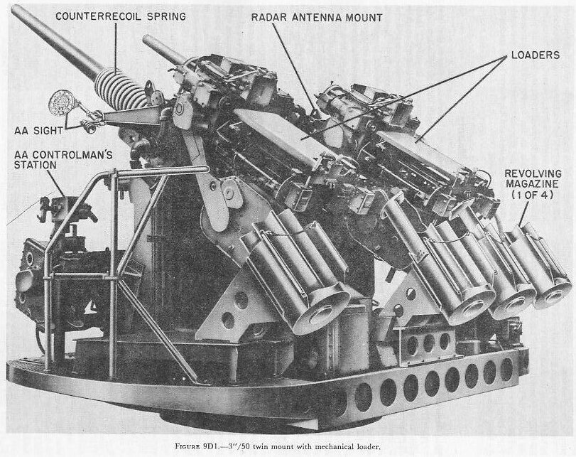
The 3"/50 rapid-fire guns are semiautomatic guns with automatic power-driven loaders, installed in dual-purpose open twin or single mounts. They are weapons primarily intended for defense against aircraft, but are so equipped that they may be used against surface targets. They were planned during World War II when a need developed for a rapid-fire gun with a larger explosive projectile. The 40-mm mount, the best rapid-fire gun at that time, was often making hits that were not stopping suicide planes or dive bombers short of their targets. The 3"/50 mount was not completed in time to be used in combat in World War II, but it has proved itself in practice firings to be very effective.
This mount is now replacing 40-mm on all types of combat ships. The twin mount shown in figure 9D1 is dimensionally interchangeable with the 40-mm quad mount. The single 3"/50 rapid-fire mount, which is similar in most respects to the twin, is designed to be substituted for the 40-mm twin mount.
The barrel of the 3"/50 is a one-piece, rifled, chambered tube, with its breech end locked to the housing by a bayonet-type joint.
The housing contains the breech mechanism and is supported in the slide. The breech mechanism is a vertical sliding-wedge breechblock type with several additional features.
The breechblock has two mechanisms for lowering it against the action of a breech-closing spring. One is a hand-operating lever employed only for initial round loading or for servicing or unloading the gun. The other breech-opening arrangement is an automatic recoil-operated cam-and-lever device.
When the breech is open, two mechanisms function, alternately, to hold the block against the action of the closing spring. One is a stiff-leg type of breech hold-down mechanism which serves as a positive lock, holding the block and locking it until the gun is loaded. It prevents breech closing until it is first released and then displaced from its holding position.
The other holding mechanism is similar to that used in the 5"/38 gun, in which the two extractors hold the breechblock down by engaging its pallets. However, their arrangement in the 3"/50 is such that, when they complete their empty-case extracting action, the extractors are poised above the pallets in the lowered breechblock, and function to hold the breechblock down only if the other device fails. This arrangement reduces the effort required to trip the extractors when a rammed round of ammunition engages them.
The gun barrel and housing are supported by the slide. When the gun is fired, they move backward and forward on bearings in the slide. A hydraulic recoil cylinder brakes rearward motion. A large counterrecoil spring drives the gun forward into battery.
The slide, gun, and housing are supported by the carriage. The trunnions, which are integral with the slide, rest in roller bearings at the top of the carriage.
A large elevating arc attached to the bottom of the slide is concentric with the trunnions. It meshes with the elevating pinion of the mount elevation power drive system.
The 3"/50 gun assembly stand is a deck-flange ring-shaped design with dimensions identical to those of the 40-mm stand. It includes the training circle and the stationary roller path. The mount is driven in train by a power motor which drives the training pinion and pulls the gun, slide, and carriage around the training circle on the stand.
General characteristics. The 3"/50 gun has the following general characteristics:
- Bore: 3-inch
- Length: 50 calibers
- Muzzle velocity: 2,700 feet per second
- Range, horizontal: 13,100 yards
- Range, ceiling: 27,300 feet
- Rate of fire (design): 45 rounds per minute
- Ammunition type: fixed, electric primed
- Fuze type: VT, PDF, BDF
- Weight complete weapon: 6,230 pounds
Dimensions, over-all:
- Muzzle to rear end: 16 feet
- Width: 38 inches
- Height: 56.8 inches
In many features of design the 3"/50 rapid-fire gun differs markedly from conventional automatic guns. These differences are chiefly in the automatic loader and the breech mechanism modifications to accommodate the automatic loader. It will be mainly these differences that will be taken up in this chapter.
9D2. Automatic Loader
The loader is an independent, electric power-driven machine mounted on the after part of the slide. It mechanically loads each gun at the rate of 45 rounds per minute as long as ammunition is served, as shown in figure 9D2, and the firing control is operated to fire.
The major loader components that will be discussed are as follows:
- Loader drive unit.
- Hopper.
- Transfer tray and shell carriage.
- Control system.
- Left side plate.
- Right side plate.
The loader drive unit consists of a 3-horsepower motor and various chain and gear drives. Most of the latter are located in the main housing, which is a large, square, box-like structure mounted on top of the gun slide. The drive motor is flange-mounted to the forward face of this housing. The drive motor drives the gearing and chains which in turn cause all the mechanical parts of the loader to function at the proper time and in the proper sequence.
The hopper, into which the ammunition is manually fed by the two shellmen, is located directly abaft the main housing and is secured to the left and right side plates.
The heart of the hopper is the hopper feed mechanism, which consists of right, center, and left shaft-and-sprocket units and right and left round-aligning attachments. The aligning attachments ensure that the ammunition is correctly loaded by the shellmen.
The right and left sprockets revolve intermittently in one direction to move ammunition to the center. The center sprocket revolves in alternate directions to accept rounds from right and left sprockets. After five rounds have been loaded, the first round will be indexed (loaded into the transfer tray for catapulting) by the center sprocket. See figure 9D3.


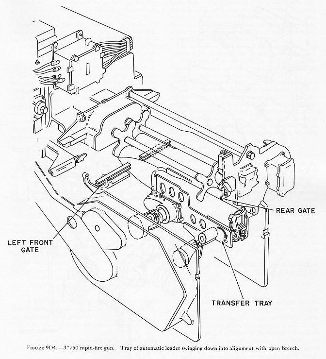
The transfer tray and shell carriage unit is the loader component that moves each round of ammunition from its index position down into line with the gun bore, and catapults it into the breech chamber. See figure 9D4. The tray is a rectangular box structure with two sprockets, one in each end of the tray, about which the endless ramming chain is looped.
The tray is supported and positioned by four arms pivoted in the right and left side plates. The two left tray arms, hence the whole tray assembly, are driven by the transfer-tray drive gears mounted in the left side plate. Drive for the rammer chain comes from concentric shafting through the left forward tray arm to the forward chain sprocket.
Secured to the rammer chain on the upper part of the tray is the shell carriage, a small L-shaped casting, to support, transport, and release the round on the tray during the ramming cycle. The cycle of operation of the transfer tray assembly begins when an indexed round from the hopper seats in the shell carriage. The four arms then begin to rotate about their pivots, translating the tray downward.
When the tray is almost in line with the breech opening, it begins to swing forward toward the breech. At this point the rammer chain begins moving the shell carriage and round rapidly forward.
When the tray is at its forwardmost point, the carriage is all the way forward, relative to the tray, and is releasing the round, which travels on into the breech as shown in figure 9D5. The tray then reverses its direction and moves aft and up to pick up another round. During this time the ramming chain moves aft to reposition the shell carriage on the tray.

The right and left side plates of the loader are similar steel forgings — roughly 4 feet long, 2 feet deep, and 6 inches thick — secured to the right and left sides of the gun slide respectively. They support all the loader subassemblies except the drive gear. In addition, each includes many loader operating and control devices and elements of the breech mechanism.
The loader control system synchronizes and interlocks the components of the loader with the breech mechanism and with each other. It consists of electrical circuits, solenoids, selector switches, automatic switches, firing keys, electrical interlocks, and other items. The mount captain's control panel is a combination control and indicator station for the loader control system.
9D3. Breech Mechanism
The breechblock is a vertical sliding-wedge type, similar in principle to that of the 5"/38. The breechblock moves as the operating shaft rotates. Much as in the 5"/38 design, in automatic operation the breechblock is lowered and the operating spring is compressed on counterrecoil when the operating-shaft crank is rotated by the operating-shaft cam plate. The breech is closed by the operating spring. A manual breech-opening mechanism is provided. A conventional, positive-type salvo latch on one end of the operating shaft prevents unintentional opening of the loaded breech before the gun has fired. The breechblock is fitted with a firing mechanism, which will be discussed later. Some of the new design features of the breech mechanism are as follows:
- A breechblock hold-down mechanism holds the breech open until the loader completes delivery of a round.
- A breech interlock mechanism prevents repetition of the loading cycle until the round has been fired and the breechblock dropped.
- A shell lock prevents the rebounding of a rammed cartridge.
- A novel extractor arrangement eliminates resistance to ammunition-ramming action.

9D4. Breech Hold-Down Mechanism
Other guns of similar design usually make use of the extractors to hold the breechblock down until a round is rammed. However, the 3"/50 rapid-fire gun makes use of the breech hold-down mechanism instead. See figure 9D6. The hold-down lever is a vertically positioned lever pivoted near its center. When the gun is in battery and the breechblock is in its held-down position, the hold-down lever bears on the hold-down arm of the breech operating shaft, preventing rotation of the shaft and closing of the breech.
The hold-down latch lever is the positive latch that secures the hold-down lever in place when the latter is holding the block down. The latch lever is disengaged in normal operation by a cam pin on the front right arm of the transfer tray.
The hold-down lever is released from the hold-down arm of the operating shaft in normal automatic loading by movement of the right extractor. When the extractor is carried forward by the rammed ammunition, the extractor push rod is thrust rearward. This actuates the transfer lever, and the thrust is transmitted through another push rod to the hold-down lever, moving it clear of the operating shaft hold-down arm and allowing the block to rise.
9D5. Extractors
The extractors are very similar to those in the 5"/38, except that the inner lugs do not normally bear on the block pallets but are poised above the pallets in a free position. In this free position, the extractors do not impose any appreciable resistance to the ammunition-ramming action, an important factor in rapid automatic loading. While the breech is opened, the extractors are held in their correct position by extractor push rods, which also aid in extracting the empty case. The right extractor push rod is longer than the left and extends through the rear of the breechblock, where it engages the transfer lever for use in the hold-down mechanism as previously described.
In the event of a failure of the breech hold-down mechanism, the breechblock will be held down by the inner lugs bearing on the pallets.

9D6. Shell Lock
The breech shell lock (fig. 9D7) functions to prevent a rammed cartridge from rebounding or backing out of the breech to foul the rising breechblock. It is a vertically sliding latch that rides in a slot in the shell-lock carrier on the face of the breech. The latch is moved upward during ramming and allows the round to pass into the bore. It is then moved down by action of the lock spring to trap the seated round. The rising breechblock pushes the shell-lock latch clear. It remains clear after firing until the extractors have moved the lip of the empty case past the shell lock, allowing extraction.

9D7. Breech Interlock
The breech interlock mechanism (fig. 9D8) is a system of mechanical linkages which function automatically to stop the loader from delivering another round to the breech whenever there is a round in the bore or the breechblock is up. The breech interlock latch lever, the first mechanism in the chain of linkages from the breech face to the loader control lever, is pivoted in the shell-lock carrier next to the shell lock and extends down the breech face, partially in front of the breech opening. When either a round is rammed or the block is raised, the latch lever is moved aside, actuating, through linkages, the loader control lever and stopping the loading cycle.
9D8. Firing Mechanism
The firing mechanism (fig. 9D7) consists of the following:
- Breechblock firing-pin insulation.
- Firing-pin assembly.
- Firing-pin cocking mechanism and sear.
The firing pin is a steel rod with a conical head that extends through the breechblock. It is similar to the 5"/38 firing pin. It provides an electrical path for electrical firing and hammer action for percussion firing. By action of the cocking mechanism, the firing pin is cocked for percussion firing and positioned for electrical firing with each cycle of the breechblock.
The cocking mechanism consists of the retracting lever and the cocking lever. The retracting lever moves the firing pin aft to keep it from shearing or fouling as the block lowers, and moves it forward into contact with the case electric primer when the block rises. The cocking lever holds the cocking sleeve aft against spring pressure during this up stroke (unless it is released by the sear if percussion-type firing is used).
It should be understood that electrical firing is the normal firing method. Percussion firing, using a special short case with percussion-type primer, is employed for clearing-round action only. This short case is used only if a projectile has separated from the case and remains lodged in the gun while an attempt is being made to unload a round through the breech.
Selection for percussion firing is made by setting an ELECTRIC-PERCUSSION lever near the left side plate of the gun.
The firing circuit of this gun cannot be closed by the firing keys alone. The various electrical interlock switches of the loader control system, such as the TRAY UP switch, must also be closed to energize the firing circuit. Thus any dangerous malfunction of the loading cycle will cause the firing circuit as well as the loader control circuit to open.

9D9. Mount Control Stations
The mount's amplidyne electric power drives may be controlled in automatic from a director or in local at the mount. There is no manual control as such, only an auxiliary handcrank for securing or servicing the mount. These mounts feature a unique local control arrangement in that there are two types of local control, local AA and local surface. Each has a separate control station. Local surface is the right gun-laying station (fig. 9D1). Local AA is the left gun-laying station. When the gun-laying drive selection is local AA, the left gun layer controls the mount in both train and elevation, and fires the gun. The left gun layer's controls consist of a ring sight, a one-man gun-laying control unit with gun firing key in right hand grip, a fire cutout indicator, and a gun-laying emergency stop control. There is no sightsetting provision at this station.
The right gun layer is responsible for starting the elevation and train drive, selecting the control station, laying and firing the guns when the drive selection is local surface, and observing correspondence between gun position and gun order signals. The right gun layer's controls consist of a telescope and open sight, a one-man gun-laying control panel, and a train cable-twist indicator (fig. 9D9). The gun-laying control panel, for a twin mount, contains a control-station selector switch, gun-firing cutout lights, power-on lights, correspondence-indicator meters to indicate correspondence between gun and mount position and the order signal, and power START and STOP buttons.
Used in conjunction with the local surface station but requiring an additional operator, is the sight setter's station (fig. 9D10). It is located directly behind the right gun layer. The sight setter operator receives sight-setting orders via telephone from the director or other fire control station and sets them into the sight setter's unit by handwheel operation. This action offsets the right gun layer's sight the required amount. The sight setter is used only with local surface gun laying.
The mount captain's station on a twin mount is located between the guns. It is to the right of the gun on a single mount. The mount captain is the supervising gunner and crew captain. His operations are directed via telephone by the control officer. He controls and directs the performance of both guns by his use of the mount captain's controls. In emergency he stops the firing of either or both guns. His panel of switches allows him to select the control station, switch to single or automatic fire, and select the gun or guns to fire.
Other elements of his control panel are master push buttons for stopping either one or both of the loaders, power-drive emergency stop buttons, and various illuminating indicators to indicate the occurrence and location of malfunctions. The gun captain's firing key must be closed before the loaders will function. The key has a latch to hold it in closed position when control of fire is to be at either left or right control station or at the director.

9D10. Ammunition
The 3"/50 gun fires fixed ammunition. A complete round is 34.74 inches long and weighs 24 pounds (the projectile, with fuze, weighs 13 pounds). Since neither the mount installation nor the associated fire control system includes provision for fuze setting, only VT-fuzed projectiles are used in AA fire. Base-fuzed and point-detonating fuzed projectiles for surface fire are also available.

9D11. Personnel
The personnel arrangement of a 3"/50 rapid-fire twin mount is shown in figure 9D11. The normal crew is composed of 11 men, as follows: a mount captain, 2 control-station men, 4 shellmen, and 4 shell passers. (One control-station man controls the mount in local surface, the other in local AA.) An additional crew member, a sight setter, is required in local surface control. The shellmen transfer ammunition from the gun carriage racks to the right and left sides of the hopper of each gun. The shell passers keep the carriage racks, called magazines, supplied with ammunition from a ready-service locker or hand-passing scuttles leading up from the handling rooms. The handling rooms are supplied by dredger hoist from the ship's magazines. The number of passers may vary, depending upon the arrangement of ready-service lockers and passing scuttles.