
A. Introduction
16A1. Tactical information
Effective operation in combat requires the collection and use of a large body of tactical information. It is desirable to know the location and disposition of all forces, both friendly and enemy, within range of the available intelligence. Before any target can be effectively engaged we must know, among other things, its range, bearing, and elevation, and the rate at which these factors are changing.
This meant that, in World War II, a way had to be found to pick up objects which lay beyond the horizon.
16A2. Sources of tactical information
Radar is the principal source of tactical information on modern warships. It may be used to detect and identify targets, and to measure their range, bearing, and elevation. Optical instruments are a secondary source of such information; in the event of power failure, they become the primary source.
Tactical information, regardless of source, is collected and evaluated by the ship’s combat information center (CIC). The functions of CIC are discussed briefly in the last section of this chapter.
B. Principles of Radar
16B1. Definition
The word RADAR is formed as an abbreviation for Radio Detection And Ranging. It is an electronic device that may be used to detect the presence of objects like airplanes or ships even in darkness, fog, or storm. In addition to indicating their presence, radar may be used to determine their bearing, distance, elevation, and speed; and to enable the operator to recognize their general character. It is one of the greatest scientific developments that has emerged from World War II. Its development, like that of most great inventions, was mothered by necessity, that of detecting the enemy before he detected us. The basic principles upon which its functioning depends are relatively simple, and the seemingly complicated series of electrical events encountered in radar can be resolved into a logical series of functions which, taken individually, may be identified and understood.
16B2. Sound-wave reflection
The principle upon which radar operates is very similar to the principles of sound echoes or wave reflection. If a person shouts in the direction of a cliff, or some other sound-reflecting surface, he hears his shout “return” from the direction of the cliff. What actually takes place is that the sound waves, generated by the shout, travel through the air until they strike the cliff. There they are reflected or “bounced off,” and some are returned to the originating spot, where the person is then able to hear the echo. Some time elapses between the instant the sound originates and the time when the echo is heard because sound waves travel through air at approximately 1,100 feet per second. The farther the person is from the cliff, the longer this time interval will be. If a person is 2,200 feet from the cliff when he shouts, about 4 seconds elapse before he hears the echo, that is, 2 seconds for the sound waves to reach the cliff and 2 seconds for them to return.
If a directional device is built to transmit and receive sound, the principles of echo, together with a knowledge of the velocity of sound, can be used to determine the direction, distance, and height of a cliff such as is shown in figure 16B1. A sound transmitter, which can generate pulses of sound energy, can be so placed at the focus of a reflector that it radiates a beam of sound. The sound receiver can be a highly directional microphone located inside a reflector (at its focal point, and facing the reflector) to increase the directional effect. The microphone is connected through an amplifier to a loudspeaker.
Then to determine the distance and direction of the cliff, the transmitting and receiving apparatus are placed so that the line of travel of the transmitted sound beam and the received echo will very nearly coincide. They would coincide exactly if the same reflector could be used for both transmitting and receiving, as is done in radar systems. The apparatus (both the transmitter and receiver) are rotated until the maximum volume of echo is obtained. The horizontal distance to the cliff can then be computed by multiplying one-half of the elapsed time in seconds by the velocity of sound. This will be essentially the distance along the line RA (figure 16B1). If the receiver has a circular scale that is marked off in degrees, and if it has been properly oriented with a compass, the direction or azimuth of the cliff is also shown. Thus, if the angle indicated on the scale is 45°, the cliff is northeast from the receiver position.
To determine height (fig. 16B1), the transmitter and receiver antennas are tilted from the horizontal position (shown by dotted lines) while still pointing in the same direction. At first the echo is still heard, but the elapsed time is increased slightly. As the angle of elevation is increased more, an angle is found where the echo disappears. This is the angle at which the sound is passing over the top of the cliff and is therefore not reflected back to the receiver. The angle at which the echo just disappears is such that the apparatus is pointing along solid line RB. If the receiver is equipped with a scale that permits a determination of the angle of elevation, the height of the cliff, AB, can be calculated from the angle and either distance RA or RB, by the use of one of the basic trigonometric ratios.

16B3. Radio-wave reflection
All radar sets work on a principle very much like that described for sound waves. In radar sets, however, a radio wave of extremely high frequency is used instead of a sound wave. The energy sent out by a radar set is similar to that sent out by an ordinary radio transmitter. See figure 16B2.

The radar set has one outstanding characteristic different from a radio in that it picks up its own signals. It transmits a short pulse and receives its echoes, then transmits another pulse and receives those echoes. This out-and-back cycle is repeated 60 to 4,000 times per second, depending on the design of the set. For Navy use the repetition rate is generally less than 1,000 cps. If the outgoing wave is sent into clear space, no energy is reflected back to the receiver. The wave and energy that it carries simply travel out into space and are lost for all practical purposes.
If, however, the wave strikes an object such as an airplane (fig. 16B2), a ship, a building, or a hill, some of the energy is sent back as a reflected wave. If the object is a good conductor of electricity and is large compared to a quarter-wavelength of the transmitted energy, a strong echo (but only a very small fraction of the transmitted energy) is returned to the antenna. If the object is a poor conductor or is small, the reflected energy is small and the echo is weak.
Radio waves travel at the speed of light, approximately 186,000 land miles per second or 162,000 nautical miles per second. Radio waves of the u-h-f and s-h-f band travel in straight lines. Accordingly, there will be an extremely short time interval between the sending of the pulse and the reception of its echo. It is possible, however, to measure the interval of elapsed time between the transmitted and received pulse with great accuracy, even to one ten-millionth of a second (1 × 10⁻⁷ seconds). The forming, timing, and presentation of radar pulses are accomplished by a number of special circuits and devices.
The directional antennas employed by radar equipment transmit and receive energy in a fairly sharply defined beam. Therefore, when a signal is picked up, the antenna can be rotated until the received signal is maximum. The direction of the target is then determined by the position of the antenna.
The echoes received by the radar receiver appear as marks of light on an oscilloscope (called “scope” for short). This scope may be marked with a scale of miles (or yards), or degrees, or both. Hence, from the position of a signal echo on the scope, an observer can tell the range and bearing of the corresponding target.
16B4. Radar methods
1. Continuous-wave method. The continuous-wave method of detecting a target makes use of the Doppler effect. The frequency of a radar echo is changed when the object which reflects the signal is moving toward or away from the radar transmitter. This change in frequency is known as the Doppler effect. A similar effect at audible frequencies is recognized readily when the sound from the whistle of an approaching train appears to the ear to increase in pitch. The opposite effect occurs when the train is moving away from the listener. The radar application of this effect permits a measurement of the difference in frequency between the transmitted and reflected energy and thus a determination of both the presence and speed of the moving target. This method works well with fast-moving targets, but not well with those that are slow or stationary. C-w systems are therefore limited in present usage.
2. Frequency-modulation method. In the frequency-modulation method the transmitted energy is varied continuously and periodically over a specified band of frequencies. The instantaneous frequency of the energy being radiated by the antenna, therefore, differs from the instantaneous frequency received by the antenna from the target. The frequency difference depends on the distance traveled and can be used as a measure of range. Moving targets produce a frequency shift in the returned signal because of the Doppler effect, however, and this affects the accuracy of range measurement. This method, therefore, works better with stationary or slow-moving targets than with fast-moving ones.
3. Pulse-modulated method. In the pulse-modulation method the r-f energy is transmitted in short pulses in which the time duration may vary from 1 to 50 microseconds. If the transmitter is turned off before the reflected energy returns from the target, the receiver can distinguish between the transmitted pulse and the reflected pulse. After all reflections have returned, the transmitter can be turned on again and the process repeated. The receiver output is applied to an indicator that measures the time interval between the transmission of the energy and its return as a reflection. Because the energy travels at a constant velocity, one-half the time interval becomes a measure of the distance traveled by the pulse to the target, or the range. Because this method does not depend on the relative frequencies of the emitted and returned signals or on the motion of the target, difficulties experienced in the c-w and f-m methods are not present. The pulse-modulation method is used almost completely in military applications. Therefore, it will be the only method discussed in this text.
16B5. Uses of radar
Radar equipments fall into three general classifications: (1) search, (2) fire-control, and (3) fighter-director (air control).
Search radars are of two categories: (1) air search and (2) surface search. These equipments are for general navigation use and early warning networks.
Fire-control radars are confined more specifically to use with certain groups or types of gun batteries and are designed to fit the requirements of the battery with which they are used.
Fighter-director radars are specifically designed to control and direct aircraft in air-to-air attack and defense. These radars are also used as search equipments in some instances.
16B6. Types of presentation
To furnish usable intelligence, a radar set must have some type of visual presentation of the target echo for the operator to observe. Cathode-ray tubes are used for this purpose.
The cathode-ray tube is a special type of vacuum tube which acts as an electronic stop watch. As shown in figure 16B3, electrons are channeled into a narrow beam by an electron gun in the neck of the tube. The electrons shoot out of the small hole at the right-hand end of the gun and hit the fluorescent screen on the large end of the tube, which glows at the point where the electrons strike. Between the gun and the screen, the electron beam passes between vertical deflection plates and horizontal deflection plates. If a variable voltage is applied to the horizontal plates, the beam can be made to sweep back and forth in a horizontal line. If a voltage is applied to the vertical plates, the beam can be made to deflect in a vertical direction. If a voltage to the vertical plates is used in conjunction with the voltage to the horizontal plates, a horizontal line deflected upward at certain points can be produced.
Type-A presentation is used to determine range, and the scope has short persistence (a target indication remains on the scope face only instantaneously). The echo causes a vertical displacement of the spot. The amplitude of the displacement depends on the strength of the returned signal pulse. The point on the horizontal base line at which the vertical displacement occurs indicates the range. Type-A presentation is shown in figure 16B4A.
The Type-B presentation (fig. 16B4B) indicates both range and azimuth angle. The vertical displacement of the echo signal indicates range, and the horizontal displacement of the echo signal indicates azimuth angle. This scope has medium to long persistence.
Type PPI (plan position indicator) presentation, shown in figure 16B4C, also indicates range and azimuth angle. In this type of presentation the electron beam is swept radially from the center of the scope to the outer edge. The sweep line follows the antenna rotation. In effect, a picture of surrounding objects is “painted” on the screen. This scope has medium persistence.


16B7. Range determination
The successful employment of pulse-modulated radar systems depends primarily on the ability to measure distance in terms of time and on a knowledge of the velocity of light. Radio-frequency energy, once it has been radiated into space, continues to travel with a constant velocity. When it strikes a reflecting object there is no loss of time, but merely a redirecting of a portion of the energy. Its velocity at the speed of light is 328 yards per microsecond. This means that it takes approximately 6.1 microseconds of radio energy to travel one nautical mile which is approximately 2,000 yards. All radar ranging is based on a flat figure of 2,000 yards per mile, and, because the speed of light (and radio waves) is so great, microseconds (μs) are used for all time determinations.
This constant velocity of r-f energy is applied in radar to determine range by measuring the time required for a pulse to travel to a target and back. The time lapse between the transmitted pulse and the echo return may be readily determined with the aid of the scope. For the purpose of illustrating how this is done, assume that a target ship is 20 nautical miles away from the radar set. Because radio energy travels 1 nautical mile in 6.1 microseconds, 122 microseconds will be required for the transmitted pulse to reach the target, or a total of 244 microseconds will elapse before the echo will return to the radar receiver.
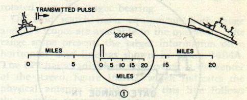
To measure this time, the horizontal sweep frequency of the scope is adjusted so that it makes one complete sweep (from left to right) during the time the transmitted pulse is going to the target and the echo is returning to the receiver.
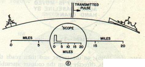
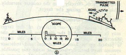
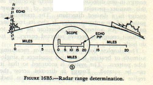
Figure 16B5 shows how the range is then determined. In 16B5-1 the transmitted pulse is just leaving the antenna. In 16B5-2, 61 microseconds later, the transmitted pulse has traveled 10 miles toward the target. In figure 16B5-3, 122 microseconds after start, the transmitted pulse has reached the target 20 miles away and the echo has started back. In figure 16B5-4, 183 microseconds after start, the echo has returned half the distance from the target. In 16B5-5, 244 microseconds after the initial pulse, the echo has returned to the receiver and appears on the scope at the 20-mile mark.

If two or more targets are in the path of the transmitted pulse, each will return a portion of the incident energy as echoes. The target farthest away (assuming they are similar in size and type of material) will return the weaker echo.
The foregoing are the basic principles of all ranging scope determinations. Usually in conjunction with the scope there is a hand crank and mechanical counter assembly. When a target is indicated on the base line, the operator turns the hand crank to move the range indicator, or gate (fig. 16B6), to the target and then reads the range, in yards, directly from the counter assembly. This is called “gating the target.”

16B8. Bearing determination
The bearing (true or relative) of the target may be determined if the direction in which the directional antenna is pointing when the target is picked up is known. Control and indicator systems have been devised that make this possible.
The measurement of the bearing of a target as “seen” by the radar is usually given as the angular position of true bearing or relative bearing. The angle at which the echo signal returns is measured by utilizing the directional characteristics of the radar antenna system. Radar antennas are constructed of a radiating element, reflectors, and directors to produce a single narrow beam of energy in one direction. The pattern produced in this manner permits the beaming of maximum energy in a desired direction. The transmitting pattern of an antenna system is also its receiving pattern. An antenna can therefore be used to transmit energy, to receive reflected energy, or to do both.
The simplest form of antenna for measuring azimuth or bearing is one that produces a single-lobe pattern. The system is mounted so that it can be rotated. Energy is directed across the region to be searched by moving the beam back and forth in azimuth until a return signal is picked up. The position of the antenna is then adjusted to give maximum return signal.
Figure 16B7 shows the receiving pattern for a typical radar antenna. In this figure, relative signal strength is plotted against the angular position of the antenna with respect to the target. A maximum signal is received only when the axis of the lobe passes through the target. The sensitivity of this system depends on the angular width of the lobe pattern. The operator adjusts the position of the antenna system for maximum received signal. If the signal strength changes appreciably when the antenna is rotated through a small angle, the accuracy with which the on-target position can be selected is great.

16B9. Altitude determination
The remaining dimension necessary to locate completely an object in space can be expressed either as an angle of elevation or as an altitude. If one is known, the other can be calculated from one of the basic trigonometric ratios. A method of determining the angle of elevation or the altitude is shown in figure 16B8. The slant range (fig. 16B8A) is obtained from the radar scope indication as the range to the target. The angle of elevation is that of the radar antenna (fig. 16B8B). The altitude is equal to the slant range multiplied by the sine of the angle of elevation.
In radar equipments with antennas that may be elevated, altitude determination by slant range is automatically computed electronically.
In equipments (air search) where the antennas do not elevate, the altitude is automatically computed from the time lapse between two echoes, one that is returned directly to the antenna and one that returns to the earth and then reflects to the antenna.

16B10. Plan position indicator
The range scope has certain limitations when it is desired to know what is happening instantaneously in all directions because it indicates only the targets in the direction which the antenna is instantaneously pointing. A master PPI, however, allows the radar operator to see the screen images of all objects surrounding his craft (within the range limitations of the equipment) because it displays a graphic plot of 360° of antenna rotation and has a screen of the necessary persistence to keep the targets visible after the antenna has rotated past the target bearing.
On most search radar equipments both range and PPI scopes are available to the operator. The range scope presents the target information on a horizontal base line, as shown in figure 16B4A. The PPI has a radial base originating at the center of the screen, figure 16B4C, which indicates the physical antenna location, and this line follows the angular antenna rotation.
A view of a PPI scope is shown in figure 16B9. The bright spots on the screen are images of objects (ships, planes, land masses, and the like) in the vicinity of the craft carrying the PPI equipment. Around the outer edge of the scope are relative and true bearing circles. Spaced evenly across the face of the tube are range circles, calibrated in miles. Thus, from the position of the images, their approximate range and bearing may be determined from the scope. A particular object of interest may be singled out for more accurate ranging by referring to the range scope.

16B11. Functional components
Radar systems now in existence vary greatly in detail. They may be very simple, or, if more accurate data are required, they may be highly refined. The principles of operation, however, are essentially the same for all systems. Thus a single basic radar system can be visualized in which the functional requirements are basically the same as for all specific equipments. In general, the degree of complication of radar circuits increases with the frequency. The microwave region lends itself to a higher degree of precision in angular measurement and for this reason modern radars operate at superhigh frequencies.
The functional breakdown of a pulse-modulated radar system generally includes six major components as shown in the block diagram of figure 16B10. The components may be summarized as follows:
- The timer (also called synchronizer or keyer) produces the synchronizing signals that trigger the transmitter the required number of times per second. It also triggers the indicator sweep and coordinates the other associated circuits.
- The transmitter generates the r-f energy in the form of short powerful pulses.
- The antenna system takes the r-f energy from the transmitter, radiates it in a highly directional beam, receives any returning echoes, and passes these echoes to the receiver.
- The receiver amplifies the weak r-f pulses returned by a target and reproduces them as video pulses to the indicator.
- The indicator produces a visual indication of the echo pulses in a manner that furnishes the required information.
- The power supply furnishes all a-c and d-c voltages necessary for the operation of the system components.

16B12. Radar system constants
Any radar system has associated with it certain constants such as carrier frequency, pulse-repetition frequency (the number of pulses sent out per second), pulse width (in microseconds), and power relation (relationship of peak and average power). The choice of these constants for a particular system is determined by its tactical use, the accuracy required, the range to be covered, the practical physical size, and the problem of generating and receiving the signals.
1. Carrier frequency. The carrier frequency is the frequency at which the r-f energy is generated. The principal factors influencing the selection of the carrier frequency are the desired directivity and the generation and reception of the necessary microwave r-f energy.
For the determination of direction and for the concentration of the transmitted energy so that a greater portion of it is useful, the antenna should be highly directive. The higher the carrier frequency, the shorter the wavelength and hence the smaller is the antenna array for a given sharpness of pattern, because the individual radiating element is normally a half-wave long. For an antenna array of a given physical size the pattern is sharper for a higher frequency.
The problem of generating and amplifying reasonable amounts of r-f energies at extremely high frequencies is complicated by the physical construction of the tubes to be used. The common tube becomes impractical and must be replaced by tubes of special design. Among these are such types as the magnetron, klystron, lighthouse triode, doorknob, acorn and peanut tubes.
These tubes of special design are normally much smaller than the conventional tubes. One of the problems involved in reducing the size of a tube is the reduction in the power rating of the tube. For example, r-f generators, such as the magnetron, are designed to radiate a large amount of power during a relatively short pulse time.
Carrier frequencies may be of the order of 100 megacycles and above. It is very difficult to amplify microwave signals; as a result, r-f amplifiers are not employed. Instead, the frequency of the incoming signals is mixed (heterodyned) with that of a local oscillator in a crystal mixer to produce a difference frequency called the intermediate frequency (i-f). This intermediate frequency is low enough to be amplified in suitable i-f amplifier stages employing electron tubes.
2. Pulse-repetition frequency. Sufficient time must be allowed between each transmitted pulse for an echo to return from any target located within the maximum workable range of the system. Otherwise the reception of the echoes from the more distant targets would be obscured by succeeding transmitted pulses. Therefore, the maximum range of a given equipment depends on the ratio of the resting time to the pulse width, provided the peak power is sufficient to return a usable echo. This necessary time interval fixes the highest pulse-repetition frequency that can be used.
In a system in which the indicator is operative during the entire interval between transmitted pulses, the repetition frequency must be very stable if accurate range measurement is desired. Because the oscilloscope screen will normally have a medium long persistence, successive traces should appear in exactly the same position to avoid blurring.
3. Pulse width. The minimum range at which a target can be detected is determined largely by the width of the transmitted pulse. If a target is so close to the transmitter that the echo is returned to the receiver before the transmitter is turned off, the reception of the echo obviously will be masked by the transmitted pulse. For example, a pulse width of 1 microsecond will have a minimum range of 164 yards. In this respect, equipments for “close in” ranging or navigation work use pulses of the order of 0.1 microsecond. For long-range equipment the pulse width is normally from 1 to 5 microseconds.
4. Power relation. A radar transmitter generates r-f energy in the form of extremely short pulses and is turned off between pulses for comparatively long intervals. The useful power of the transmitter is that contained in the radiated pulses and is termed the peak power of the system. Because the radar transmitter is resting for a time that is long with respect to the operating time, the average power delivered during one cycle of operation is relatively low compared with the peak power available during the pulse time.
A definite relationship exists between the average power dissipated over an extended period of time and the peak power developed during the pulse time. The overall time of one cycle of operation is the reciprocal of the pulse-repetition frequency (PRF). Other factors remaining constant, the greater the pulse width, the higher will be the average power; and the longer the pulse repetition time, the lower will be the average power. Thus:
average power / peak power = pulse width / pulse-repetition time
The operating cycle of the radar transmitter can be described in terms of the fraction of the total time that r-f energy is radiated. This time relationship is called the duty cycle and may be represented as:
duty cycle = average power / peak power = pulse width / pulse-repetition time
High peak power is desirable in order to produce a strong echo over the maximum range of the equipment. Low average power enables the transmitter tubes and circuit components to be made smaller and more compact.
C. Types of Radar Equipment
16C1. Search radar
Search radars used for general navigation and early warning nets do not require great precision in ranging and bearing, but do require the ability to locate targets at fairly long ranges. Therefore, they are normally designed with high power, wide beam angle, and fairly long pulse widths. Their target resolution (ability to determine bearing and range accurately) is within approximately ±2° and ±200 yards.
16C2. Fire-control radar
Fire-control radars require only the range necessary for controlling the guns with which they are associated. However, they also require precision target resolution. To accomplish this they are designed with low power, short pulses, and narrow beam angles. Their primary purpose is to furnish to the fire-control systems accurate bearing and range of targets in order that the computers and other components of a gun-laying system may be fast, effective, and efficient.
16C3. Fighter-director radar
Fighter-director radars are specifically designed for the control of friendly aircraft, particularly at night or during heavy weather. With this equipment control personnel are able to direct friendly aircraft effectively in air-to-air battle when the friendly aircraft cannot see the enemy. These radars are designed with great power and maximum target resolution. They may also be used as search and special early warning equipments.
16C4. Airborne radar
Radars for aircraft are of the same general types as land or shipboard radars except they are physically much smaller. Both search and fire-control radars are successfully used in aircraft.
D. Special Purpose Equipments
16D1. Identification, friend or foe (IFF)
The age-old problem of distinguishing friend from enemy in warfare increased greatly when radar and aircraft came into combat use. Radar supplied target information at greater than visual ranges and it was therefore necessary to identify targets, both surface and air, as early as possible in order to take the initiative. As deadlier and faster aircraft have been developed, the identification problem has increased. Although a radar can detect aircraft at long ranges, a radar scope shows aircraft, whether friend or enemies, only as spots of light. With modern, high-speed aircraft the captain of a ship cannot afford to wait until the aircraft are identified by visual means before he prepares his ship for battle. He must identify the aircraft at a great distance from the ship; and if he does not identify the aircraft, he must assume them to be enemies and order his aircraft to intercept them as far away from the ship as possible.
The problem of identification led to the development of an electronic system that permits friendly forces to identify themselves automatically before approaching near enough to threaten the security of other naval units. The foregoing electronic system is called, appropriately enough, identification, friend or foe, or IFF. In practice, the “foe” part of the name could be omitted because, as a foe does not carry identifying equipment, he is identified by his lack of identification rather than by his identification.
The IFF system consists basically of a pair of special transmitter-receiver units, one set aboard the friendly ship and the other aboard another friendly unit. Because space and weight aboard aircraft are limited, the airborne system is smaller and lighter and requires less power than the shipboard transmitter-receiver. The airborne equipments are automatic and do not operate until triggered by a signal from a shipboard unit.
IFF systems are designated by mark numbers. In order to avoid confusion between IFF systems and fire-control systems, the IFF mark number is a Roman numeral (Mark III) whereas the fire-control number is an Arabic numeral (Mark 29).
1. Theory of operation. The IFF system operates as follows: An air search radar operator sees an unidentified target on his radar scope. He turns on the IFF transmitter-receiver, which transmits an interrogating, or “asking” signal to the airborne transmitter-receiver. The interrogating signal is received by the airborne unit, which automatically transmits a characteristic signal called an identification signal. The shipboard system receives the signal, amplifies it, and displays it on the radar scope, or on a separate indicator scope. When the radar operator sees the identifying signal and identifies it as the proper one, he knows that the aircraft is friendly. However, if the aircraft does not reply when interrogated, or if it sends the wrong identifying signal, the ship must then assume the target is an enemy and defensive action must be taken.
2. Security aspects. You can easily see from the foregoing text that the enemy could do a tremendous amount of damage if he were able to imitate the characteristics of our IFF identification signals. For this reason, strict security measures are observed with regard both to identification signals and to IFF equipment. The identifying signal usually is (1) coded, (2) changed frequently, and (3) given a high security classification.
IFF equipment is: (1) specially designed, (2) wired to destroy itself on the impact of a crash or at the will of the control personnel, and (3) given a high security classification.
3. Types of IFF equipment. Early IFF equipments were of two types: (1) the Interrogator-Responsor, and (2) the Identification Set. The Interrogator-Responsor performs two functions: (1) to transmit an interrogating signal, and (2) to receive the reply. The Identification Set, known as a transponder, also performs two functions: (1) to receive the interrogating signal, and (2) to reply automatically to the interrogating signal by transmitting an identifying signal.
4. Types of interrogation. There are two types of interrogation—direct and indirect. The interrogation is direct when the interrogating signal that triggers the transponder is a pulse from radar equipment. The interrogation is indirect when the interrogating signal is a pulse from a separate recognition set operating at a different frequency from that of the master radar.
Early IFF systems used direct interrogation. However, direct interrogation proved unsatisfactory because the transponder was required to respond to radars that differed widely in frequency and pulse-repetition frequencies. Therefore, the later IFF systems use indirect interrogation within a special frequency band reserved for IFF operation.
Due to the security classification of the current IFF systems, this text will not attempt to present any technical details of IFF operation.
16D2. Countermeasures
Radio countermeasures (RCM) prevent the enemy from using his radar and communications equipment effectively, produce false signals on the enemy receivers, and prevent the enemy from using countermeasures on our own radar and communications equipment (counter-countermeasures).
In order to use countermeasures most effectively against an enemy radar, you should know the following things about the enemy radar facility: (1) frequency, (2) pulse width, (3) pulse-repetition frequency, (4) peak power, (5) receiver bandwidth, (6) time constants of the receiver coupling circuits, (7) antijamming features, (8) amount of shielding, (9) type of indicator, (10) antenna beamwidth, (11) type of scan, and (12) use of the radar.
Special equipment has been developed for use in analyzing r-f transmissions. This equipment includes search receivers, which search all the frequencies that can be used; panoramic adaptors, which measure the frequency, strength, and type of modulation of a transmission; and pulse analyzers, which measure the pulse rate and width.
Radar countermeasures (RadCM) fall into two distinct types: nonelectronic, which consist of reflectors, strips of aluminum foil, decoys and prediction devices; and electronic, which consist of search receivers, panoramic adaptors, pulse analyzers, jamming transmitters, signal generators, and noise modulators.
1. Nonelectronic countermeasures. Units called “corner reflectors” are used to present strong echoes to enemy radar signals. When placed carefully in many locations, they return strong echoes that appear to the enemy operator to be a large naval force.
“Rope” was the code name for long streamers of aluminum foil. This foil, cut in lengths of about 400 feet, is dropped by aircraft within range of an enemy radar. The foil twists and turns as it falls, thus presenting many different effective lengths to the enemy radar. Some of these lengths are highly resonant at the frequency of the radar and, therefore, appear as strong target signals.
“Decoys” consist of a wide variety of devices. Some of the most effective are balloons towing strips of aluminum foil. These strips, which vary in length, present strong reflections over a fairly wide band of frequencies. Other decoys are aircraft towing streamers of metal foil and floats carrying wire mesh or foil reflectors.
“Window” is the code name for short strips of tuned aluminum foil. The foil is cut to slightly different lengths so that it reflects at the frequency of enemy radar. The strips are packaged and dropped over enemy territory. While fluttering to the ground, they present a multitude of targets to the enemy radars. Thus, enemy searchlight and tracking radars follow the strong echoes presented by the window and cannot be made to track on the lesser echoes presented by the aircraft.
The Radar Prediction Device (RPD) also proved to be a very effective CM device during World War II. The RPD was simply a relief map of the enemy territory with a flashlight bulb at the location of the enemy radar set. The shadows cast by mountains or other features of the terrain indicated weak detection or blind spots in the enemy radar beam. When a blind spot was found, aircraft used it as an avenue of approach to avoid early detection.
2. Electronic countermeasures (ECM). Many electronic equipments have been developed for use in analyzing enemy transmissions and in jamming enemy receivers. ECM has two general classifications: passive and active. Passive ECM is merely using the receiving equipment to detect the presence of the enemy by the use of his radar or radio r-f transmissions. Active ECM is the addition of transmitting equipment to the receiving equipment to jam the enemy transmissions.
3. Antijamming measures. Antijamming measures, or counter-countermeasures (CCM), are used to reduce the effect of enemy jamming on our own equipment. In receivers, some of the most important CCM devices are special filters that pass only the important parts of echo signals, thus rejecting as much of a jamming signal as possible. In the transmitters, a great many of the radar equipments have tunable magnetrons (oscillators) whose frequency may be varied at regular intervals to prevent an enemy jamming transmitter from locking on its frequency.
16D3. Radar beacon principles
RAdar beaCONS, called RACONS, are similar in operation to the transponder equipment. They are passive until triggered by a radar signal. When triggered by suitable radar pulses, the beacon emits a coded series of pulses which appear on an aircraft’s radar indicator and identify the beacon. A navigation fix can be obtained from one or more racons of known position.
Racons were used extensively in World War II on the ground, in ships, and in planes for air navigation, ship navigation, paratrooper rendezvous, aircraft rendezvous, bombing, shore bombardment, and amphibious operations. A modern use of racons is in pilotless aircraft. A beacon in a pilotless aircraft gives a means of following the trajectory of the missile.
The racon is a direct type of transponder and therefore is designed to cover a wide range of frequencies and to respond to many different pulse rates and durations.
16D4. Airborne early warning radar
The U.S. Navy now has in extensive use radar equipments called Airborne Early Warning (AEW) systems. These are special shipboard and aircraft radar systems that work together as a single unit.
In these systems the aircraft is able to re-transmit or relay to the shipboard unit the information from the plane’s search radars. The ship then has a PPI display from the aircraft’s search radar equipment. It can be easily understood how this will extend the range of radar for the ship by great distances. For example, a plane at a 1,000-foot altitude will have a minimum radar detection range, on a target 50 feet high, of 55 miles. If the plane is relaying radar information to a mother ship 50 miles away, then the ship has an effective search range of 105 miles in the plane’s direction. If a relay is directly over a mother ship at 5,000 feet, then the ship has an effective 360° search range, to radar horizon, of 100 miles.
E. Principles of Optics
16E1. Function of optical instruments
The optical instruments used in naval fire control present a magnified image of the target to the observer’s eye. At the same time, the observer sees an image of a reticle, or reference mark, located inside the instrument itself. By accurately superimposing the reticle image on the target image, the observer can establish an accurate line of sight to the target. The rangefinder, by establishing two separate lines of sight, makes it possible to find the target range by triangulation.
To form the reticle and target images, an optical instrument must control the path of the light that passes through it. It does so by the use of lenses, prisms, or mirrors, or some combination of these elements. This section briefly reviews the behavior of light as it passes through optical elements.
16E2. Nature of light
Light is a form of energy. It travels from one point to another in the form of waves. Except for their wavelengths and frequency, light waves are identical with other types of electromagnetic radiation, such as radio waves and gamma rays. The wavelength of visible light ranges from approximately 0.35 micron to 0.70 micron. (A micron is one thousandth of a millimeter.)
The color of light depends on its wavelength. In order of increasing wavelength, the colors are violet, indigo, blue, green, yellow, orange, and red. Radiation of longer wavelength than visible red is called infrared, or heat radiation. Beyond infrared are the radio waves. Radiations shorter than visible violet are, in the order of decreasing wavelength: ultraviolet, X rays, gamma rays, and cosmic rays.
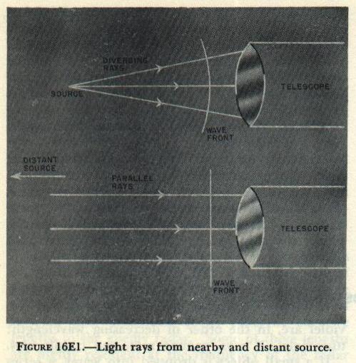
In the study of optical instruments it is convenient to trace the path of light rays, rather than waves. A telescope or similar instrument will receive only a small part of the light emitted by the source. Each wave that enters the instrument, therefore, is only a small part of a sphere. If a wave comes from a nearby source, the part of it that enters the instrument will be strongly curved. And the rays (radii of the spherical wave) that enter the instrument will be diverging. But if the source is at a great distance, the part of the wave that enters the instrument will be nearly flat; for all practical purposes it can be considered a plane. Since the rays are perpendicular to the wave front, the rays that enter an optical instrument from a distant point can be considered parallel. Figure 16E1 should make this clear.
In figure 16E1, the source of light is a single point. But a telescope is most often used to observe fairly large objects, such as enemy ships. In this case, of course, not all the rays that enter the telescope will be parallel. But all the rays that enter the instrument from any one point on the object will be parallel, as shown in figure 16E2. In this figure, the solid lines represent rays from the top of the object; the broken lines represent rays from the bottom of the object.

Light travels at tremendous speed: approximately 186,000 miles per second in air. In a vacuum, its velocity is slightly higher. In a denser medium, it moves more slowly. For example, the velocity of light in water is about 140,000 miles per second; in glass it ranges from 95,000 to 127,000 miles per second, depending on the optical density of the glass. When light passes from one medium into another of different density, its velocity changes. This change in velocity makes it possible for an optical instrument to control the path of light, to form images, and to magnify them.
16E3. Reflection
When light, traveling in air, strikes the surface of a mirror, most of it is reflected back into the air. Figure 16E3 shows the path of a ray of light reflected by a mirror. The incoming ray is the incident ray. The normal is an imaginary straight line, at right angles to the mirror surface, passing through the point of incidence. The angle of incidence is the angle between the incident ray and the normal, and the angle of reflection is the angle between the normal and the reflected ray. The law of reflection states, first, that the angle of incidence is equal to the angle of reflection; and, second, that the incident ray, the reflected ray, and the normal all lie in the same plane.
When light, traveling in glass, strikes an air surface, a part of the light will be reflected back into the glass; the rest will enter the air. At zero angle of incidence, about 5% of the light will be reflected back into the glass. As the angle of incidence is increased, the amount of reflection increases rapidly. When the angle of incidence becomes greater than the critical angle, all of the light will be reflected back into the glass; none of it will enter the air. (The critical angle for various types of glass, at an air surface, varies from 37° to 43°.) For angles of incidence greater than the critical angle, the inner surface of the glass acts like the mirror in figure 16E3, and the reflection from this surface follows the same laws. This property of a glass-air surface, called total internal reflection, is used in many optical instruments.
Mirrors are occasionally used in optical instruments to deviate the line of sight. But, if the angle of incidence is greater than the critical angle, internal reflection at a glass-air surface is usually used for this purpose. Figure 16E4, for example, shows how the line of sight may be deviated through an angle of 90° by internal reflection at the diagonal face of a right-angle prism.
For this purpose, a prism has two important advantages over a mirror. First, a prism may be more rigidly mounted than a mirror, and is thus less subject to misalignment or breakage. Second, the reflecting surface of a prism will reflect all the incident light, whereas a mirror will reflect only about 90%.


16E4. Refraction of light
When light passes from air into glass, its velocity will decrease. It will resume its original velocity when it leaves the glass and enters the air. If a ray of light strikes an air-glass or a glass-air surface at an oblique angle, its change of speed will result in a change of direction. Figure 16E5 shows why this is so.
The diagonal lines in the figure represent the approaching light waves. Since they are coming from a distant source, they are parallel. As each wave enters the glass, various points along the wave front will slow up successively, and as a result the entire wave front will change its angle. Since the direction of movement, shown by the ray, is at right angles to the wave fronts, the light bends as it enters the glass. The opposite effect occurs when the waves leave the glass. Now the various points along the wave successively increase their speed. As a result, the emergent waves are parallel to those that entered the glass. And the emergent ray is parallel to the incident ray, although it has been displaced to one side.

Figure 16E6 illustrates some of the terms used to describe the refraction, or bending, of light. The law of refraction states that light bends toward the normal when it passes into a denser medium; it bends away from the normal when it passes into a less dense medium. The exact angle of bending may be easily calculated. It depends on the angle of incidence, and on the optical density of the two media. Optical density is expressed as index of refraction. (The index of refraction of a vacuum is one; the index of refraction of air is approximately one. The various types of optical glass range from approximately 1.5 to 1.96.)

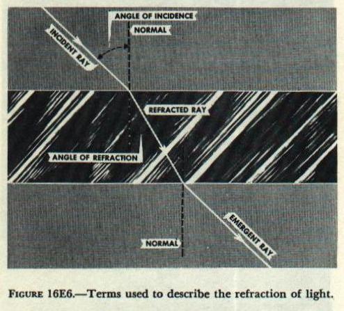
When the two glass surfaces are parallel, as in figure 16E6, the emergent ray is parallel to the incident ray. When such elements occur in optical instruments (as, for example, in the end windows of rangefinders), they do not deviate the line of sight. However, if the two glass surfaces are not parallel, the line of sight will be deviated, as in figure 16E7. When the ray enters the glass at the first surface, it bends toward the normal. As it leaves the glass, at the second surface, it bends away from the normal. The net result is a deviation of the ray toward the base of the prism. Thin prisms are used in rangefinders to deviate the line of sight through a small angle.

16E5. Image formation
Figure 16E8 shows the path of parallel rays of light on passing through two prisms mounted base to base. Each ray will be deviated toward the base of the prism it passes through. As a result, the upper rays are deviated downward, and the lower rays are deviated upward. If the surfaces of the two prisms are rounded off to form a convergent lens, as in figure 16E9, each ray will have a different angle of incidence, and will therefore bend to a different degree. The ray that passes through the center of the lens is normal to both surfaces, and therefore does not bend. Such a ray is said to lie on the optical axis of the lens.
If the lens is perfect, all rays parallel to the axis will meet at a single point, called the focal point of the lens. Every lens has two focal points, one on each side. The two focal points are equally distant from the lens. The distance from either focal point to the center of the lens is the focal distance, or focal length of the lens.
By applying the law of refraction at each surface of the lens in figure 16E9, it can be seen that, if a source of light is placed at the focal point, the diverging rays that strike the lens will be deviated toward the axis, and will be parallel when they emerge from the lens. The behavior of light on passing through a convergent lens can be summarized by these statements: parallel rays will be converged to the focal point, where they will cross; convergent rays will be more strongly convergent after passing through the lens; divergent rays will be less divergent after passing through the lens.


Figure 16E10 shows three rays of light diverging from a point source, and passing through a convergent lens. All the rays from A that pass through the lens converge and meet at point B. Point B is therefore the image of A. Note that B is itself a source of light, since rays diverge from it just as they do from A. If a sheet of paper is held at B, the image may be seen as a bright point on the paper. If B lies between the lens and the observer’s eye, the image may be inspected directly.
A target or other object is visible when it reflects light toward the observer. Each point on the target, unless it is black, may be considered a point source of light. For each of these points, a convergent lens will form a corresponding image point, behind the lens. These image points together form a recognizable image of the whole target. In the study of any optical instrument, it is often desirable to know the size and location of the image. This information may be obtained from a scale drawing, as in figure 16E11.

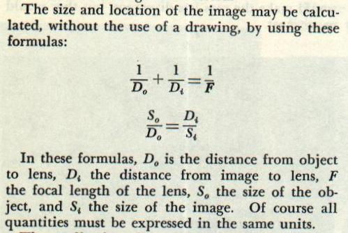
The application of these formulas will reveal several things: (1) If the object distance is twice the focal length, the image distance will also be twice the focal length, and the image will be the same size as the object. (2) If the object distance is equal to the focal length, the image will lie at infinity. (3) If the object distance is more than one but less than two focal lengths, the image distance will be greater than two focal lengths, and the image will be larger than the object. (4) If the object distance is greater than twice the focal length, the image will be smaller than the object. (5) If the object distance is less than the focal length, no real image is formed.


16E6. Virtual images
Figure 16E13 shows the path of several rays diverging from a point source of light, O, when the source lies between the lens and its first focal point. These rays are highly divergent. The lens makes them less divergent, but it does not have the power to bring them to a focus. However, an observer on the right side of the lens may see the point O by looking through the lens. Since the observer is accustomed to assuming that light travels in straight lines, it will appear to him that the rays from source O are actually coming from point I. Point I is therefore an image of O. However, if a sheet of paper is held at I, no image will be formed on the paper. Point I is therefore not a real image. Point I is said to be a virtual image of point O. Note that the virtual image is farther from the lens than the object itself.
Figure 16E14 shows how a scale drawing may be used to determine the size and location of a virtual image. Note that, whereas the real image formed by a convergent lens is inverted, the virtual image is erect. A single convergent lens may be used, therefore, as a simple magnifying glass.
A magnifying glass is most effectively used by holding it close to the eye. The object distance is adjusted until the image appears in sharp focus when the muscles of the eye are completely relaxed. The object distance will then be equal to the focal length of the lens, and the virtual image will lie at infinity.


16E7. Simple telescope
A telescope is used to provide, to an observer’s eye, an enlarged image of a distant object. A telescope can be made by using a combination of two or more lenses. The first lens, called the objective, forms a real image of the distant object. Since rays diverge from this real image just as they do from the object itself, the observer may examine the real image through a second lens, called the ocular. The ocular serves as a simple magnifying glass. It forms an enlarged virtual image of the real image formed by the objective.
Figure 16E15 shows the path of rays through a simple telescope. The real image formed by the objective lens is, of course, inverted. The image may be erected in either of two ways. One way is to add an erector lens. Many telescopes make use of erector lenses. A few telescopes, and most binoculars, use prisms to erect the image. This is accomplished by means of internal reflection at the various prism faces. Figure 16E16 shows several different ways in which prisms may be used to erect an image.
To provide a fixed line of sight through a telescope, a reticle may be added. The reticle is a flat piece of glass on one surface of which suitable reference marks, often two lines intersecting at a right angle, have been engraved. The ocular serves as a simple magnifying glass to provide an enlarged virtual image of the reference marks on the reticle.


16E8. Correction of aberrations
From the foregoing discussion it would appear that a useful gun-sight telescope could be made with only four optical elements: an objective lens, an erector lens, an ocular lens, and a reticle. The actual instruments we use, however, contain a larger number of lenses than this. The additional lenses are necessary to correct the aberrations of the optical system.
The surface of a lens is part of a sphere, because spherical surfaces are relatively easy to grind. Every lens in a commercial optical instrument therefore has either two spherical surfaces, or one spherical and one plane surface. But light, in passing through a spherical surface, does not behave in an ideal manner. No single lens can actually converge parallel rays to a single point. These departures from ideal performance are called aberrations.
White light is a mixture of colors. The angle of refraction at an optical surface depends on two factors: the angle of incidence and the index of refraction. But the index of refraction of any medium, such as glass, depends on the color of light. Blue light, for example, will be much more strongly bent than red light. A lens will behave in the same way. Blue rays will be bent to a focus closer to the lens than the red rays. Because of this chromatic aberration, a lens will form a separate image for each color, and no two of these images lie in the same plane. As a result, the observer sees a fuzzy, indistinct image.
When parallel rays strike a spherical lens surface, those rays nearest the edge of the lens will be bent to a focus nearer the lens than rays striking the lens near its center. This effect is called spherical aberration. Because of spherical aberration, each zone of the lens produces a separate image, and no two of these images lie in the same plane.
The optical designer has several variables to work with: the radius of curvature at each surface, the distance between surfaces, and the index of refraction of various kinds of glass. By a suitable manipulation of these variables, the designer is able to make the aberrations of one part of the optical system cancel those of another part, so that the system as a whole can produce an image of useful sharpness. As a result, optical instruments are complex, and the spacing of the various elements must be maintained precisely.
F. Types of Optical Equipment
16F1. Gun-sight telescopes
A gun-sight telescope provides the observer with an enlarged image of the target and thereby makes the target easier to see. At the same time, it establishes a line of sight from gun to target by presenting an image of the reticle crosslines superimposed on the target image. A pair of telescopes is provided at each gun installation. One of these is used by the pointer, the other by the trainer. The trainer controls the train of the mount or turret, and the pointer controls the elevation of the guns, so that the crossline image in both telescopes is superimposed on the target image. Then, provided the axes of the telescopes have been previously adjusted to intersect the axis of the gun at that range, the axis of the gun bore will be aimed directly at the target.
However, unless the target is at point-blank range, the gun will not be fired with its axis pointing along the line of sight. The gun must be elevated above the line of sight, because of the curved trajectory of the projectile. The gun must usually be deflected laterally from the line of sight because of wind, projectile drift, and relative motion of gun and target. The necessary elevation and deflection angles are computed by the director. When this information is fed into the sight-adjusting mechanism, the optical axis of the telescope is moved until it diverges from the axis of the gun bore by the required angle. Then, when the crosslines are superimposed on the target image, the gun will have the deflection and elevation necessary to hit the target.
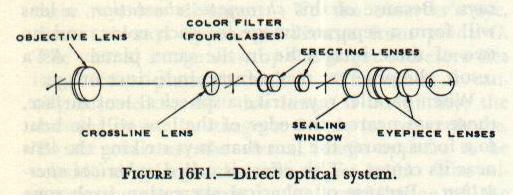
Turret sight telescopes include all the gun-sight telescopes used in the turrets of battleships, and in the turrets and single-purpose main-battery mounts of cruisers. The optical system may be either of two general types: direct or indirect. Figure 16F1 is a diagram of the direct optical system. The optical axis of the telescope lies along the line of sight, and the sight mechanism provides the elevation and deflection angles by moving the whole telescope.
The objective lens forms an inverted real image of the target. This image falls on the engraved surface of the crossline lens, or reticle. Between the reticle and the erecting lenses are the four color filters. (Only three of these are actually colored; the other is plain glass.) These filters are so mounted that the operator can bring any one of them into the line of sight. A filter of the proper color will, under some conditions, increase the contrast of the target image, and decrease the glare from sky and water. The erecting lenses erect the target image, and form a real image of the crosslines superimposed on that of the target.
The indirect optical system, shown in figure 16F2, is basically similar to the direct system. The principal difference is that the line of sight is twice reflected by prisms, so that the axis of the telescope lies at right angles to the line of sight from gun to target. A telescope of this type may be mounted with its main axis either vertical or horizontal. Because telescopes with the indirect type of optical system are often mounted vertically, they are usually called turret periscopes.

Antiaircraft gun-mount telescopes differ from turret telescopes in that the observer’s line of sight through the eyepiece is not parallel to the line of sight from gun to target. If the target is in the same horizontal plane as the telescope, the observer must look downward into the eyepiece in order to see the target image. This feature makes it easier to track an overhead target without discomfort.
Figure 16F3 represents the optical system of a typical antiaircraft gun-mount telescope, the Mark 67. Light from the target is reflected first in the head prism, and then in the erecting prism, before it enters the objective lens. The roof prism turns the line of sight back toward the observer, and at the same time bends it upward through an angle of about 35 degrees. The sight-setting mechanism controls the position of both the head prism and the erecting prism. The head prism rotates on a horizontal axis, to control the elevation of the line of sight. The erecting prism controls deflection of the line of sight by turning on an axis at right angles to that of the head prism.

16F2. Lead-computing sights
Lead-computing sights are used with automatic guns to provide a solution to the short-range antiaircraft fire control problem. The sight, like the gun-sight telescope, establishes a line of sight to the target. The gun axis is elevated at the necessary angle above the line of sight when the proper range inputs are made to the sight mechanism.
The short-range antiaircraft problem is more complex than the long-range antiaircraft and surface fire control problems. Unless the attacking aircraft is flying directly toward the gun, the elevation and deflection of the line of sight will change rapidly as the target approaches. Because of its high speed, the target may move a considerable distance while the projectile is in flight. The gun must therefore be aimed ahead of the target, if target and projectile are to reach the same point at the same time. In other words, the gun axis must lead the line of sight by the proper angle in both elevation and deflection. The more rapidly the line of sight changes in elevation or deflection, the greater the lead angle must be.
As its name implies, the lead-computing sight computes the necessary lead angle. The operator turns and elevates the sight to track the target. When he tracks successfully, the reticle image will appear to be superimposed on the target at all times. The sight mechanism, however, causes the operator’s line of sight to lag behind the axis of the instrument. The more rapidly the sight is moved, the greater this lag will be. Since the operator uses this lagging line of sight to track the target, the axis of the sight, and therefore the axis of the gun, will lead the target by an angle proportional to the rate at which the sight is moved.
The lead-computing sight mechanism is based on one or more rapidly spinning gyroscopes. When the sight is turned or elevated, thus tending to change the direction of the gyro axis, the gyro tends to undergo precession. The force it exerts on its restraining mechanism will be proportional to the rate at which the direction of its axis is changed. The sight mechanism applies this force to the optical system of the sight, in such a way that the line of sight lags by the proper angle.
Figure 16F4 represents the optical system of a lead-computing sight using a single gyro. The system does not magnify the target image. The operator observes the target directly, through the two windows and the clear reflecting glass. The lamp at the top of the diagram is used to illuminate the reticle. The reticle is located exactly at the focal point of the collimating lens. Rays of light from the reticle are therefore parallel after they pass through the lens, and after they are reflected toward the operator by the reflecting glass. Because these rays are parallel, the reticle image appears to lie at infinity, and the reticle will not change its apparent direction when the operator moves his head from side to side.

The force of precession exerted by the gyro controls the angle of the reflecting glass. Although the angle of this glass has no effect on the line of sight to the target, it determines the apparent position of the reticle. Assume that the sight is trained to track a target moving across the field of view. The force exerted by the gyro will turn the reflecting glass, so that the reticle image tends to lag behind the target. In order to keep the reticle image superimposed on the target, the operator must make the sight axis lead the line of sight to the target. When the sight is elevated to track a target passing overhead, the gyro will tilt the reflecting glass so that the reticle image tends to lag below the target. Again the operator must lead the target in order to track it.
Most often, the line of sight to the target will be changing in both deflection and elevation. Then, when the target is tracked, the gyro will turn and tilt the reflecting glass at the same time. Thus the lead angle generated by the sight mechanism will be correct in both magnitude and direction.
Figure 16F5 is a diagram of the optical system of a lead-computing sight with two gyros. The line of sight from the target is reflected by each of the four mirrors. The two lead-angle mirrors are controlled by the two gyros, so that the optical line of sight lags behind the sight axis when the sight is moved. The objective forms a real image of the target, in the plane of the reticle. Target image and reticle are examined through the eyepiece. The system provides an enlarged erect image of the target. Since the image is inverted by reflection from the four mirror surfaces, no erector lens is necessary.

16F3. Boresight telescope
When the sight-setting mechanism is set for zero elevation and zero deflection, the lines of sight through the gun-sight telescopes must intersect the axis of the gun bore at the target. The boresighting operation is used to check this adjustment. One observer is stationed at each telescope, and one at the gun breech.
All observers sight on the same target; if the three lines of sight are observed to be on target at the same time, the gun is correctly boresighted. The lines of sight through the telescopes are, of course, established by the crosslines on their reticles. The boresighting equipment provides a line of sight through the gun bore.
Boresighting equipment is of several kinds. For the very small guns, such as the 20-mm antiaircraft guns, it consists of a breech attachment containing a peep hole, and a muzzle attachment with cross-lines. The gun axis is aimed at the target by using the peep hole and crosslines as an open sight. The larger case guns may use a boresight with self-contained optics. This equipment converts the whole gun into a telescope. The muzzle fitting contains the objective lens; the breech fitting contains the reticle and eyepiece.
The 5"/38 and all bag guns may use a breech bar and boresight telescope. Figure 16F6 shows how this equipment is mounted. The breech bar is secured by screws to two threaded holes in the breech. The telescope housing is screwed into the breech bar, and locked rigidly in place by turning the locking ring up against the breech bar. The telescope is secured in its housing by a spherical bearing and four adjusting screws.
The telescope has a simple, straight-line optical system, consisting of objective, reticle, erecting lenses, and eyepiece lenses. The position of the objective may be adjusted, to bring the image into focus on the reticle, by turning the parallax-adjusting ring. The muzzle disc fits into the muzzle of the gun; the hole in the center of the disc lies on the axis of the gun bore.
16F4. Rangefinders
The rangefinder consists essentially of a system of optical units assembled in a long, cylindrical tube. The tube is supported by a mount, which permits training the rangefinder on the target. Modern rangefinders are generally supported on mounts integral with turrets or director housings, leaving only the protruding ends exposed. On its forward surface, the tube has a window at each end. Through these windows, the operator establishes two separate lines of sight to the target.

The range may therefore be read directly from the scale when the lines of sight from P and S intersect at the target.
There are two basic methods by which the operator can determine when the two lines of sight intersect at the target. These methods give rise to the names of the two types of rangefinders used by the Navy: the stereoscopic rangefinder and the coincidence rangefinder. With a coincidence rangefinder, the operator uses only one eye, and examines the two target images through a single eyepiece. The two lines of sight intersect at the target when the two target images appear to coincide. With the stereoscopic rangefinder, the operator uses both eyes; he examines the separate target images through separate eyepieces. The operator’s eyes fuse the two images into a single image, as they do when observing the two images formed by a pair of binoculars. In each line of sight is a reticle, and the two reticle images are also fused into a single image. The operator adjusts the line of sight until the reticle image appears to lie at the same distance as the target image. The rangefinder has then measured the angle θ, and its scale indicates the range.
The theoretical requirements for a coincidence rangefinder are very simple. It must present magnified images of the target, so that coincidence of the two images may be accurately established. It therefore uses a telescope in each line of sight. The two lines of sight must point toward the target from the two ends of the rangefinder. They must, however, come together at the center of the instrument, so that both may be seen by a single observer. Each line of sight is therefore reflected twice: once at the end and once at the center of the rangefinder.
In figure 16F8, A and B represent the two lines of sight to the target. L and R are mirrors, each mounted at an angle of 45 degrees to the tube axis. Each line of sight will therefore be reflected through 90 degrees. After reflection, each line of sight passes through a telescope objective lens. C represents two 45-degree mirrors, one above the other. Each line of sight will be reflected through 90 degrees by one of these mirrors. After the second reflection, the two lines of sight will coincide. The two images may be seen by the observer, at E, through a single eyepiece.

When the two lines of sight coincide, as in figure 16F8, the observer sees a single, unbroken image of the target. Part A of figure 16F9 shows a slight improvement on the optical system of figure 16F8. The two mirrors at L and R have been replaced by pentaprisms. In these prisms, the line of sight is reflected twice. The images are therefore not reversed from left to right, as they would be by single mirrors. The pentaprisms cannot depend on total internal reflection, since light strikes both reflecting surfaces at less than the critical angle; these surfaces are therefore silvered. Pentaprisms are used only in relatively small rangefinders.
If the target is not at infinity, the two lines of sight will not be parallel, and they will not coincide at E. The broken line B′ represents the line of sight from a target at medium range. This line diverges from B by the angle of convergence, u. The target image, as seen by the observer, will be broken in the center by a horizontal line; the upper half of the image will be displaced with respect to the lower.
The operator can measure the angle of convergence, and therefore the range, by turning the line of sight B′ through the angle θ. Part B of figure 16F9 represents the system actually used. Two thin prisms or wedges, comprising the compensator, have been inserted in the B′ line of sight. A prism, it will be remembered, deviates light toward its base. If the two wedges deviate B′ through the angle of convergence, the two lines of sight will then coincide, and the target image will appear unbroken. The compensator is so constructed that the angle of deviation is continuously variable. This is accomplished by rotating the two wedges through equal angles, in opposite directions.
Figure 16F10 shows how this system works. If it is remembered that a prism always deviates light toward its base, the figure is self-explanatory. As the diagrams show, the wedges must be rotated through an angle of 90 degrees to change the deviation from minimum to maximum. This makes possible the use of a long, uncrowded range scale.

The optical system of an actual rangefinder is somewhat more complex than that shown in figure 16F8, although it will not be described in detail here. The rangefinder includes a supplementary optical system for use in calibration. It also has a halving adjustment, by which the two images can be adjusted so that there is no overlapping or duplication. The astigmatizer, which may be inserted in the line of sight when necessary, distorts the image so that the image of a point appears as a vertical line. This makes it possible to use a coincidence rangefinder to range on a searchlight at night. And the rangefinder does not use two simple mirrors to reflect the images toward the observer, as shown at C in figures 16F8 and 16F9. It uses a coincidence prism for this purpose.
Figure 16F11 is a simplified diagram of a coincidence rangefinder, showing the coincidence prism. This prism is rather complex, and difficult to represent in a two-dimensional drawing. It consists of three separate prisms. The two larger prisms are cemented together. Half of the cemented area is silvered.
Light from the left pentaprism is reflected twice in the large vertical element of the coincidence prism group. Half of this light—the part that forms the lower half of the image—then strikes the silvered surface and is reflected toward the single reflecting prism. The rest, forming the upper half of the image, misses the silvered surface; it passes out through the top of the prism, and is discarded.
Light from the right pentaprism, after deviation by the compensator wedges, is reflected upward at the lower face of the diagonal prism. The part of this light that forms the lower half of the image strikes the silvered surface, where it is reflected upward and discarded. The rest, forming the upper half of the image, continues on to the single reflecting prism. The single reflecting prism reflects both halves of the image toward the eyepiece.

The use of a stereoscopic rangefinder depends on the stereoscopic vision of the operator. The relative distance of two objects may be determined in several ways: by intervening objects, relative sizes, aerial perspective, focusing, convergence, and image doubling. Of the effects listed, convergence and image doubling require binocular vision—the use of both eyes at once. The stereoscopic rangefinder makes use of both these effects.
The stereoscopic rangefinder, like the coincidence type, uses two telescopes, with their lines of sight extending toward the target from the two end windows. The telescopes provide magnified images of the target. And the effective distance between the observer’s eyes is equal to the base length of the rangefinder.
The observer’s eyes fuse the two target images, one from each telescope, into a single unbroken image, just as they do when observing the target through a pair of binoculars. In each telescope of the rangefinder is a reticle. The observer fuses the two reticle images into a single image. Because the apparent angle of convergence of the two reticles is fixed, the reticle pattern appears to lie at a certain fixed distance in space. If the target happens to be at that distance, target and reticle will appear to be equally distant from the observer. The operator adjusts the compensator wedges until the target and reticle appear to lie at the same distance. He may then read the range on the calibrated scale.
To demonstrate the stereoscopic effect, hold the index finger of one hand vertically, at arm’s length in front of the face. Hold the index finger of the other hand vertically in front of the face, at a shorter distance. Now shift fixation from one finger to the other, and note the muscular effort required to change the angle of convergence. Note also that when either finger is fixated, the other appears doubled. Figure 16F12 illustrates this point.
Figure 16F13 provides a simple exercise to show how image fusion is possible. Hold a sheet of cardboard on edge, perpendicular to the paper, midway between the two dots. Place the head about 12 inches from the page, so that the eyes can look squarely at the paper as in reading. Adjust the cardboard so that each eye sees only one of the dots. Now, while looking at the dots, relax the eyes and try to look through the paper. After a short time the two dots will fuse into a single, blurred image. Without losing fusion, refocus the eyes until the two dots appear as a single, sharp image.

Figure 16F14 will illustrate the effect of apparent distance difference. Use the sheet of cardboard, as with figure 16F13. Fuse the upper pair of dots, and bring them into sharp focus. Then change fusion to the lower pair of dots. Change back and forth several times. Because of the difference in convergence, and the consequent doubling of one pair of dots, the upper pair will appear to be closer.
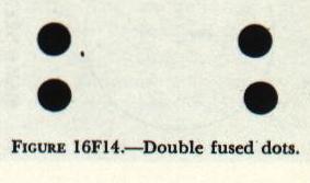
Figure 16F15 is a simplified diagram of the optical system of a stereoscopic rangefinder. (Each of the two telescopes contains an erector system, which has been omitted from the drawing for the sake of simplicity.) The two circles at the upper left show the views seen by the two eyes before adjustment of the compensator wedges. The target arrow will appear to be considerably more distant than the reticle diamonds.

Figure 16F16 represents the image of reticles and target as actually seen through the eyepiece group. Note that the reticle image consists of one row of diamonds and four rows of vertical lines. The center diamond is used for ranging on the target. All the marks in any one row appear to be at the same distance from the observer. The row of lines immediately above the diamonds appears to be more distant than the diamonds, and the top row appears to be still more distant. The row immediately under the diamonds appears to be nearer than the diamonds, and the bottom row appears to be nearer still. When the center diamond has been superimposed on the target, the rows of vertical lines make it possible to estimate the range of bursts or splashes without readjusting the compensator wedges.
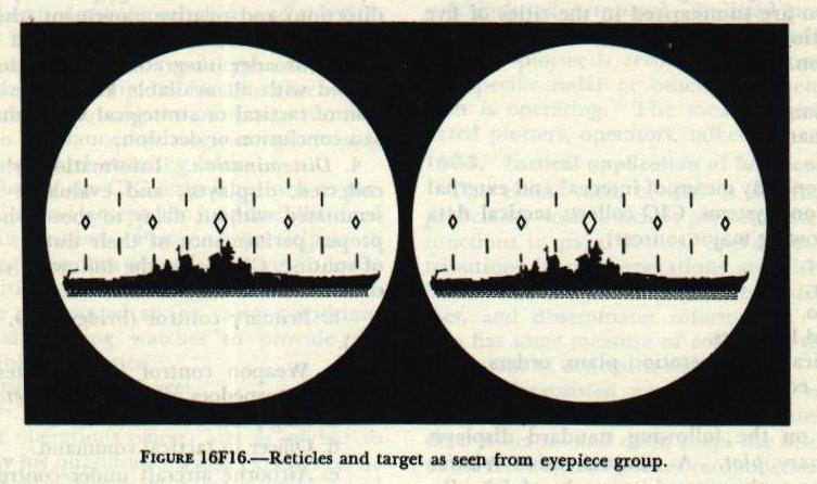
The horizontal distance between any two adjacent marks in the same row corresponds to five mils in deflection. Thus deflection spots can be made without training the rangefinder off the target. Because it is more useful for spotting, as well as for ranging on fast-moving targets such as aircraft, the stereoscopic rangefinder is more widely used than the coincidence rangefinder.
G. Combat Information Center (CIC)
16G1. Mission and functions
The ship’s combat information center (CIC) is the organization which processes tactical information. Its mission is to keep command and control stations informed of the tactical situation at all times. In general terms, this means that CIC (usually referred to as Combat) must maintain an up-to-date, comprehensive picture of the disposition of all friendly and enemy forces within range of the available intelligence. CIC must maintain the picture in a form which will permit rapid interpretation of each new bit of information, integration of new information with all other data, and immediate transmission of the new information with its significant implications to all who need it in the performance of their duties. Procedures employed by CIC in accomplishing its mission in any tactical situation are summarized in the titles of five routine functions: Collection, Display, Evaluation, Dissemination, and Control.
1. Collection. By means of internal and external communications systems, CIC collects tactical data from the following major sources: (a) Radar, (b) Sonar, (c) Radio, (d) Visual lookouts, (e) Publications (operation plans, orders, etc.), (f) ECM equipment.
2. Display. Data collected by CIC are displayed prominently on the following standard displays: (a) Summary plot — a comprehensive relative display of positions and/or tracks of all forces; (b) Geographic plot (DRT) — a true display of positions and/or tracks; (c) Surface plot — a relative display of surface forces; (d) Disposition diagram — shows all ships in a formation; (e) Status boards; (f) Strategic plot; (g) Air plot — displays all air contacts.
3. Evaluation. Evaluation (appraisal, determination of the tactical significance of information collected and displayed in CIC) is accomplished on two levels: (a) the routine application of the principles of dead reckoning and relative movement to all tactical data; (b) the broader integration of the information thus gained with all available knowledge and information of tactical or strategical value, and the arrival at a conclusion or decision.
4. Dissemination. Information which has been collected, displayed, and evaluated must be disseminated without delay to those who need it for proper performance of their duties. As a matter of routine, CIC keeps the following command and control stations informed: (a) Primary control (bridge, CO, tactical plot, etc.), (b) Weapon control, (c) Flag plot, (d) Officer in tactical command, (e) Airborne aircraft under control.
5. Control. Having collected, displayed, evaluated, and disseminated each new bit of information, CIC may be directed by command to take action or to assume certain control functions, including control of search radars, passive ECM equipment, communications with other ships, assigned airborne aircraft, jamming on enemy radar frequencies, interception of air contacts, and direction of antisubmarine attacks.
16G2. Personnel
Normally, all Radarmen and Radarman strikers are assigned to the CIC division for duty and for administrative purposes. The CIC division is a part of the operation department. The operations officer is the head of the department, and the CIC officer usually is the division officer.
The key personnel in CIC are:
- Evaluator. An officer experienced in tactics (normally the operations officer) acts as adviser to command. He is charged with general supervision of the combat information center during general quarters.
- CIC officer. Charged primarily with the operation and maintenance of the combat information center and the equipment connected therewith. His duties include the collection and distribution of operational information, supervision of lookouts, maintenance of records, and preparation of reports.
- Controller. Charged with the responsibility for controlling aircraft in the air-defense area. He is qualified to perform all CIC functions, and is particularly proficient in all phases of aircraft control.
- CIC watch officer. Takes charge of the watch in Combat. He sees that CIC logs are properly maintained and that watch routine is observed.
- Gunnery liaison officer. Responsible for passing target indication data from CIC to gunnery control stations. He is proficient in the interpretation of radar indications and his duties include effecting the transfer of targets from search radars to fire control radars.
- Enlisted personnel. Men are generally designated plotters, operators, talkers, or recorders, identified by the specific plot or equipment they are operating.
16G3. Tactical application of functions
The effectiveness of CIC is determined by the proficiency with which it performs the five routine functions in naval tactical operations. CIC’s contributions include:
- Radar-assisted navigation. CIC plots the ship’s track, obtains radar fixes, determines set and drift, keeps the bridge informed of all hazards, and makes recommendations for appropriate courses and speeds.
- Formation and screen maneuvers. CIC keeps a plot of all friendly forces, solves relative-movement problems for changing stations, and makes recommendations to the bridge for appropriate course and speed changes.
- Gunnery coordination and liaison. CIC indicates available targets, designates specific targets to gunnery control stations as directed by command, and assists in acquisition of targets by using target-designating systems to transfer designated targets from search radar to fire control radar tracking.
- Naval gunfire support. CIC performs duties similar to radar navigation while supplying gunnery control stations with data for fire control solutions—course, speed, set and drift, bearing and range to the target, and location of front lines of own troops on shore.
- Torpedo attack control. CIC solves relative movement problems and makes recommendations to the bridge for approach and retiring courses and speeds.
- Antisubmarine operations. CIC uses both sonar and radar information continuously to track the submarine and other assisting or attacking ships. CIC recommends courses and speeds for execution of search plans and is prepared to furnish firing times for throwing weapons and depth charges if required.
- Air control. In air control operations, CIC performs all five of its basic functions. Combat controls communications with airborne aircraft, controls aircraft on routine patrol stations, and controls interception of air contacts when directed.
16G4. Conclusion
The combat information center is, briefly, an agency for the collection, display, evaluation, and dissemination of tactical information, and for facilitating the use of that information. CIC is not something strange and complex, nor is it merely a radar plot or an antisubmarine plot under another name. It provides a marked clarification and simplification of work for command. The captain receives information as he needs it; and he is free to concentrate on his decisions and carry the burden of command. He also has, in CIC, an organization to which he can delegate secondary decisions and control duties as the occasion may require.