
A. Historical Preface
15A1. General
Fire control is the technique of delivering effective fire on a selected target. It includes the material, personnel, methods, communications, and organization necessary to harass, damage, or destroy the enemy. Within the Navy, however, the term has been customarily restricted to the control of gunfire, while more specific terms such as torpedo fire control and rocket fire control are used for other weapons.
The fundamental problem of gun fire control is to direct the gun in such a way that the projectile will hit the designated target. If the target is stationary and close enough, the problem is not difficult. Complications are introduced by increasing the range, by shooting from a moving platform such as a ship, by shooting at moving targets, and by shooting many guns at the same target with centralized control. The increase in range increases the time of flight of the projectile, allowing gravity to exert its influence over a longer period of time and to cause the projectile to fall more and more below the projected axis of the bore of the gun. The increase in time of flight also permits greater accumulation of errors caused by motion of own ship and target or by ballistic factors such as wind and drift. As battle range and target speed increase, requirements for accuracy of original measurements and in more complex computations increase.
15A2. Early fire control
The development of fire control as a science and as an art has been pretty much the product of the last century and a half. Prior to 1800, there was no need for elaborate fire control, because the guns themselves were inaccurate except at short ranges. Battle ranges of the period were pistol shot (about 50 yards) and half pistol shot (about 20 yards).
Sighting consisted chiefly of setting the guns in azimuth, and of leveling them by eye. Sometimes allowance for the curvature of the trajectory was made by “sighting by the line of metal.” This was done by aligning the top of the breech and the top of the muzzle with the point of aim, causing the gun to be elevated by the amount of the taper of the gun from breech to muzzle.
Little attempt was made to regulate initial velocity. Powder charges were estimated, and the projectile load was variable. One shot or several shots were used for a charge, and at close quarters guns were frequently loaded to the muzzle with grape shot.
Nautical gunners became aware of the problem of deck tilt for obvious reasons. One early device for correcting for the roll of the ship was a round shot suspended from a spar. The gunner watched this improvised pendulum swing with the roll of the ship, and just before it was parallel to the mast, he applied his slow match to the touch hole of the piece. Another practice depending upon the roll of the ship was that of firing at the crest of the roll to increase the range.
15A3. Development of fire control
Improvements in fire control were for many years correlated with increases in gun range.
The table, GUNNERY RANGES 1862–1948, shows how gunnery ranges have been increased during the past century.
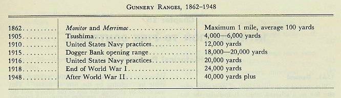
Since these improvements represent specific attempts to develop particular phases of fire control, each of these aspects will be separately treated in the succeeding paragraphs.
15A4. Gun sights
Gun sights introduced early in the nineteenth century consisted of fixed front and rear sight points so adjusted that the line of sight across their tips was parallel to the bore of the gun. The only advantage was a definite means of leveling the gun at the point of aim, although elevation could be adjusted within small limits by regulating the coarseness of the sights taken across the points.
Improvements in guns and powder during and after the War Between the States resulted in such increases in range and accuracy that graduated gun sights became a necessity. A movable leaf, adjustable both vertically and laterally, was fitted into the rear sight. Correction for drift caused by the adoption of rifling in big guns was approximated by inclination of the rear sight bracket.
Toward the end of the nineteenth century, the sight telescope was developed. The sight telescope was mounted in such a way that the line of sight could be offset from the axis of the bore of the gun to correct for range, drift, and relative motion of gun and target. Elevation scales were graduated in accordance with proving-ground data, and the weight and composition of powder charges were carefully regulated. An improvement in operation was effected by installing two sights and dividing the responsibility of keeping on target between the pointer in elevation, and the trainer in train.
15A5. Development of fire control instruments
Naval gunnery practices demonstrated the need of precise measurement of quantities basic to the solution of the fire control problem and to exact and continuous computation. It is of interest that the first steps were taken by young officers who were concerned with practical performance.
Range measurement. When it was found that estimation of range was no longer sufficiently accurate, mechanical aids were sought. The first of these was the stadimeter, adapted to this purpose by 1898. The stadimeter was crude, and was accurate only for short ranges, but it embodied a principle used later in the coincidence rangefinder, which provides sufficient accuracy for surface fire control under good visibility conditions. Later the stereoscopic rangefinder was developed, giving equal accuracy for surface targets and making it possible to range on fast-moving air targets. Recently radar has carried range accuracy out beyond the shooting limit of the guns, and is not dependent upon clear visibility.
Computing devices. The largest and most important corrections in fire control are those that compensate for the relative motion of own ship and target. This relative motion usually causes continuous, and sometimes rapid, change in values of range, relative bearing, and in case of air targets, elevation. Since there are two distinct time lags between the initial determination of the line of sight and the actual impact or burst of the projectile—the time lag between the initial measurement and the solution of the problem, including transmission of the orders to the gun, and the time of flight of the projectile—relative motion will introduce enough error to cause a miss if its effects are not predicted and properly taken into account.
It is, of course, possible to compute on paper, for a specific set of conditions, the correct gun positioning orders in elevation and deflection for any one particular instant. This method is still used for post-firing analysis, but never was of much value in actual practice, as it takes too long and provides no means of continuing the solution to correct original errors or to include further change in the position of the target.
Early in the twentieth century, an improvement in computation was brought about by graphic plotting. A graphic plot (for a surface target) consists of a series of ranges and bearings of the target, set down on paper, from which it is possible to determine the approximate course and speed of the target. This method provided a valuable supplement to the paper computation, but was soon supplanted by a further refinement, which plots range against time. The advantage of this procedure is that it makes possible the determination of the rate at which range is changing (range rate) and so makes it feasible to predict the range at the end of the time of flight. In practice, the fire of main-battery guns was controlled in this way for a time, but the important contribution of graphic plotting was that it established the basic principle of the mechanical rangekeeper.
Briefly, this basic principle is that if present range is determined, and if the rate and direction at which range is changing can be computed from the speeds and courses of target and own ship, then the range at a later instant can be determined by computing the change of range for any convenient time interval and adding this change of range to the original value of observed present range, assuming that the range rate remains constant during the period of the computation. This computation can be used to keep the range up to date while the problem is being solved, and to predict for change during the time of flight of the projectile.
The most elementary rangekeeper, consequently, has mechanisms for entering observed present range, for determining the range rate, for multiplying the range rate by increments of time, and for accumulating the changes of range. This process is called generating present range. The element of time is supplied by building a clock into the rangekeeper.
The same reasoning can be applied to bearing. The observed value of relative bearing becomes the starting point of the computation. The bearing rate (the rate at which bearing is changing) can be computed and multiplied by increments of time, and the resulting increments of bearing can be used to modify the original value of bearing.
Actually, the simplest mechanical rangekeeper ever used by the Navy, the “Baby Ford,” was designed to perform these three functions: (1) computing range rate, (2) computing bearing rate, and (3) generating present range.
Once the fundamental rangekeeper was adopted, the natural course of development was to add mechanical means of adjusting for wind, gun ballistics, and variations from standard initial velocity; to add the third dimension of elevation for air targets, and to generate elevation in AA rangekeepers; to refine the method of correcting initial errors in observed values; and generally to shorten the time required for solution.
Corrections for deck motion. A solution for the problem of firing accurately from a rolling and pitching ship did not appear until World War I. This solution depends on the second important adaptation of a child’s top—the gyroscope—to Navy use.
The gyro’s property of maintaining its spin axis fixed in space was first used on shipboard in the gyrocompass, which always points to true north and is not affected by the magnetic fields of the ship. The gyro compass itself is important in fire control, as it establishes a system of polar coordinates from which the relationship of own ship and target motion to the earth may be determined.
To correct in fire control for the inclination of the deck caused by the roll and pitch of the ship, the property of gyroscopic rigidity is again used. A gyroscope is so mounted that, as its axis of spin establishes and maintains the true vertical, it makes possible the establishment of a reference plane in the horizontal. The position of the ship with respect to this reference plane is measured and fed into the computer as constantly changing inputs to the problem.
Communications systems. Since the equipment and stations comprising a fire control system are widely dispersed for various reasons (visibility, protection, etc.) adequate communications are very important. As fire control installations became more complex and elaborate, the relaying of shouted orders gave way first to rubber hose stretched between stations, then to metal voice tubes; but neither was satisfactory. The first reliable system was the telephone, which has the necessary clarity and flexibility. Sound-powered telephones and interior communications systems make it possible for a control officer to talk to whole groups of men at many stations. Today, communications have become a major factor in the coordination of ship and gun control. A special station for the collection, evaluation, and dissemination of combat information called the Combat Information Center (CIC) has been established to assist the commanding officer in planning a correct course of action, and to assist Command and Fire Control in the execution of that plan. It handles the innumerable transmissions of intelligence within the ship and from outside.
In addition to the telephone systems, which are adequate for voice commands, fire control makes great use of a variety of mechanical and electrical means of communicating information from one station to another. These include mechanical shafting, buzzers, light signals, and synchro systems for transmitting gun orders and other quantities that may be represented as angular displacements.
15A6. Director control
Under the old system of pointer fire, each gun was practically an independent unit. Each gun crew worked out its own sight settings, and except for being told when to commence and when to cease firing, each gun crew fired at will. As fire control and communications improved, it became evident that a single control officer should direct the work of the battery. From his elevated station he could estimate or measure range, could transmit sight settings to the guns, and could observe the fall of shot and estimate corrections known as spots.
It soon became evident that with all guns firing individually it was almost impossible to spot with any accuracy. Buzzers were later used at all the guns to give the signal for firing. This was an improvement, but the guns still went off at various times during the sounding of the buzzer. The next step was the installation of a master firing key in series with the firing circuits of all the guns. When that master key was closed, all ready guns fired.
The control station soon became much more than a station from which verbal orders were issued. A new instrument called a director was installed there. This was at first a pair of “master gun” sights that were offset by the necessary lead angles and sighted on the target. The movements of these sights were transmitted electrically to the gun mounts, which duplicated sight motion by matching pointers. Later a director having a built-in analog computer, one part of which became known as a “dummy gun,” was used. The movements which positioned the dummy gun were transmitted to the mounts, to be followed in elevation and train by matching pointers or, in later installations, by automatic control equipments.
The dummy gun idea was eventually given up, but the director remains. It has taken on new functions, such as measuring range, bearing, and elevation, and spotting or otherwise correcting the solution of the problem.
Today the quantities measured at the director are sent to the computer in a protected plotting room below decks. The computer, in addition to solving the fire control problem and transmitting the gun orders to the gun, also sends signals to the director to keep the sights positioned on the target if the solution is correct. If the solution should be in error, some director systems are provided with devices whereby discrepancies between the ordered positioning rates of the director and the actual rates of the target can be measured and introduced as corrections to the computer’s solution. This procedure is known as rate control.
15A7. Spotting the fall of shot
As battle ranges have increased, increasing importance has been assumed by spotting, or observation of the actual fall of shot. Optical spotting was found to be inadequate at long range, even from the highest station on the ship. Kite balloons were tried in World War I, but proved to restrict ship maneuvers too greatly. Spotting planes were found effective for spotting in range, but not in deflection. Radar has proved to be the best means to date for spotting, as it is almost perfect in range and reasonably accurate in deflection.
15A8. Flexibility of control
Today, gunfire is almost independent of ship maneuvers, and is not, as in the past, limited by tactics. By providing duplicate control and computing stations, batteries can be divided to cover several targets at once or may all be directed at the same target. Further, the destruction of any one station does not make it impossible for the battery to continue its fire.
15A9. Aircraft fire control
Within the memory of many living men, the airplane has developed from an amusing and improbable experiment to the point that the air arm has achieved full parity with the Army and the Navy, and within the Navy itself it has become virtually axiomatic that command of the air over the sea is requisite to the control of the sea.
The carrier provides a floating base for tactical aircraft, making it possible, within the limited range of fighter planes and bombers of suitable size, to employ them tactically in naval battle with the fighting ships themselves completely hidden from each other over the horizon, as was the case in the battles of the Coral Sea and Midway in World War II, or to give tactical support to troops and to maul supply lines far inland, as was proved by the Korean conflict.
As aircraft have become heavier and faster, the variety of weapons carried has increased, comprising guns, bombs, rockets, and torpedoes. Development of aircraft capabilities has caused a corresponding evolution of fire control instruments, as solution time for the problem has become shorter. Individual gun sights and bombsights are being displaced progressively by complete fire control systems. Some of these will be discussed in detail in a later chapter of the present book.
B. Modern Fire Control Systems
15B1. Batteries
For a long period, the batteries of a single ship frequently consisted of guns of various sizes. Because of the difficulty of controlling and spotting the fire of so many batteries, the practice of using guns of the same size and ballistic characteristics in a given battery was adopted. This practice also resulted in a simplified system of supply for ammunition and replacement parts.
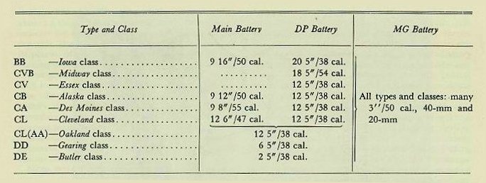
The size and number of guns in a battery depends upon the type of ship. Batteries are generally referred to as:
Main battery. The guns of the largest caliber aboard a ship. The term is sometimes extended to indicate the weapon of greatest potential effect. For example, the main battery of an aircraft carrier is its planes; of a submarine, its torpedoes; of certain landing craft, the rocket battery.
Dual-purpose battery. Guns which are adaptable for use against either aircraft or surface targets. In ships which have a single-purpose main battery, the dual-purpose battery may be called the secondary battery. Many other ships have a dual-purpose main battery.
Machine-gun battery. Permanently emplaced automatic weapons of all calibers, used chiefly against aircraft.
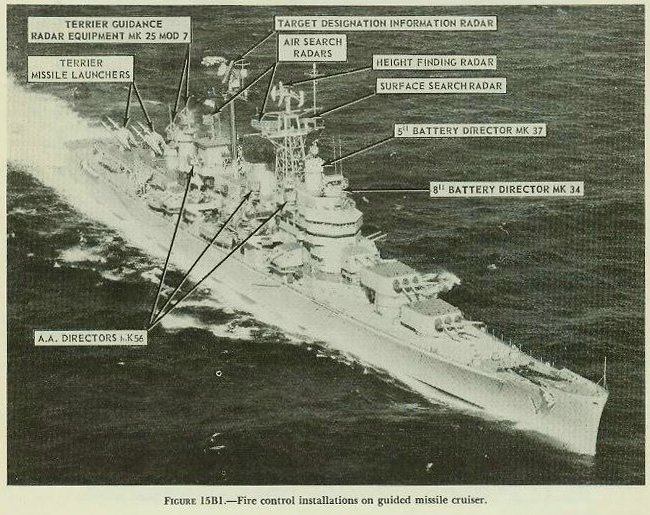
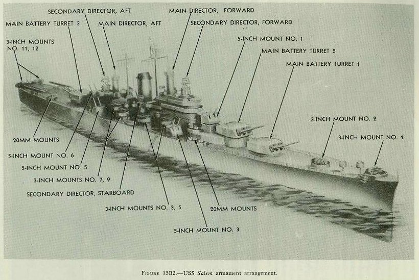
Some typical examples of combatant ship gun batteries are shown in Figures 15B1 and 15B2.
15B2. Fire control systems
The exact composition and arrangement of a ship’s fire control system depends upon such factors as the type of ship and the size, number, purpose, and effective range of its guns. In general, fire control systems have the following characteristics:
- The primary method of fire is director fire. When the number and arrangement of guns in a battery permits, the battery may be controlled from one station, or the fire may be divided and controlled from several points against multiple targets.
- Provision is made for observations to establish present target position and to spot the fall of shot.
- Computers figure the predicted position of the target, the ballistic corrections, and corrections to compensate for roll and pitch of the ship. These data are used to compute gun orders in train and elevation which are transmitted to the guns.
- Gun orders keep the guns constantly positioned in space, ready to fire whenever the firing key is closed.
- Provision is made for stand-by methods of control if the primary method is inoperative.
- Efficient communications are provided, with duplicate systems for transmitting information.
- Provision is made for control of the battery at night, including the control of star shells and searchlights.
15B3. Battleship systems
On a modern battleship, the two primary main-battery directors are the highest on the ship, the forward one being about 120 feet above the waterline, the after one about 75 feet. Either director, together with equipment in the plotting rooms, can control all or part of the main battery. Also, any one of the four secondary-battery directors can be used to control all or part of the main battery. In addition, equipment in each turret permits individual, but less effective, control of the turrets independently of the directors and plotting rooms. Five optical rangefinders, one in each main-battery director and in each turret, provide main-battery ranges. Fire control radars in the fire control tower and in each main-battery director provide radar range (and bearing) for the main battery.
Below the waterline are the forward and after plotting rooms, each of which contains rangekeepers, stable verticals, graphic rangekeeping devices, switchboards, and other instruments. Information is received in plot from the radars, rangefinders, and directors, and is combined with other information obtained from various sources. Computed quantities are transmitted to the guns for their control. Either plotting room may control any part of the battery. Auxiliary computing equipment is provided in each of the three turrets, so that each may fire independently.
The secondary battery has four directors, each of which has its own rangefinder and radar, and may control all or any part of the dual-purpose battery. There are two secondary (dual-purpose) battery plotting rooms similar to those of the main battery, except that they contain no graphic plotting devices. Each is equipped with two computers, two stable elements, the necessary indicating instruments, and switching equipment. With director-controlled fire it is possible to engage four secondary battery targets simultaneously with independent illumination control.
The heavy machine-gun battery is equipped with a separate director and fire control system for each of its mounts. Many of the directors are equipped with radar. Decentralized control permits firing at many targets at once, and facilitates target acquisition. Flexibility of control is provided by cross connections permitting the heavy machine-gun directors to control the adjacent dual-purpose mounts, and the secondary-battery directors to control the heavy machine-gun mounts.
The light machine guns (20-mm) are equipped with individual lead-computing sights.
15B4. Cruiser and destroyer systems
Cruisers have fire control installations similar to those of battleships, except that there are only two directors for the dual-purpose battery (i.e., the secondary battery on cruisers with turrets; the main battery on AA cruisers). Figure 15B1 shows the fire control installations on a guided missile cruiser, U.S.S. Boston (CAG-1). On guided missile cruisers of this class, the after 8-inch triple turret and the after 5-inch twin gun mount have been replaced by two twin Terrier missile launchers.
Destroyers have only one director and one plotting room for the dual-purpose (main) battery. The control of dual-purpose and machine-gun batteries on cruisers and destroyers is similar to that on battleships, but they can engage a smaller number of targets simultaneously, because of the smaller number of guns and directors.
15B5. The fire control problem
The principal subject of the next several chapters is the fire control problem. This term has come to mean the entire series of measurements and computations used in the control of weapons, beginning with the designation of the target and the type of fire, and ending with the destruction of the target. For all batteries, the problem of gun fire control is solved in five steps:
- Establishing the present position of the target. The first step in the solution of the problem is to establish the present position of the target with relation to the ship by measuring its range, bearing, and, for air targets, elevation.
- Computing lead angles. Lead angles in elevation (called sight angle) and in bearing (called sight deflection) are computed to allow for wind, gun ballistics, and relative motion of own ship and target during the time of flight of the projectile. This is the principal function of all rangekeepers and computers.
- Correcting for motion of gun platform. Corrections are computed to counteract the effect of the constant rolling and pitching of the ship.
- Making up gun orders. Since the guns are so mounted that they can move only in train and elevation, all the foregoing information is converted into gun positioning orders, and is constantly corrected, so that the guns are continuously positioned for firing.
- Correcting fall of shot. In case of inaccuracy of computation, the projectiles may fail to hit the target. Errors are determined by observation and are corrected by the application of corrections known as spots.
15B6. Presentation of the fire control problem
The fundamental considerations in the solution of the fire control problem are the same for both surface and air targets. Since the surface problem is less complicated, it is considered in this text before the air problem.
It should be clearly understood that the emphasis in this text is upon principles, rather than upon details of specific installations. Descriptions of specific equipment are limited to the most commonly used examples of each type. Further information is to be found in the publications of the Bureau of Ordnance.
Methods of use are subject to change; consequently, this publication describes procedures only as illustrations of the capabilities of the equipment. The practicing gunnery officer is referred to fleet publications of most recent date for guidance in this respect.
It is emphasized that the student is expected to receive only an introduction to fire control in this text. The expert gunnery officer is made by constant experience and by the detailed study of all fire control gear with which he is associated, particularly that on his own ship.
15B7. Symbols and definitions
Fire control has developed its own language, and the study of the subject requires familiarity with the definitions and symbols of which this language is composed. Gunnery definitions, as standardized by the Fleet Training and Readiness Branch of the Office of the Chief of Naval Operations may be found in appendix E. They are adequate for general use, but their application varies somewhat among different fire control systems. The Bureau of Ordnance has established standard fire control and torpedo control symbols of a more restricted nature, the most useful of which are to be found in appendix F. Fire control symbols and nomenclature, as used in the sections of this book not limited to specific equipment, have been prepared to agree with the most recent current practice. It should be noted that symbols and nomenclature are subject to modification for individual equipments, and that all symbols, nomenclature, and definitions are subject to change by the Bureau of Ordnance and the Chief of Naval Operations. Throughout this text, symbols and definitions occur as required by the subject matter. In some cases the standard definitions have been paraphrased to make them easier to understand.