U.S. Navy 600 psi Steam Plant — Controls, Gauges & Oil Burner Fronts
These nine photographs were taken in the fireroom of a U.S. Navy warship — the spaces where the Black Gang tended the oil-fired boilers that produced superheated steam for the ship’s propulsion turbines. They show the gauge boards and firing-control station from which the watch managed combustion and steam conditions, the main steam pressure and superheated steam temperature gauges, the engine order telegraph repeaters that relayed bridge orders, and the burner fronts where fuel oil and atomizing steam entered the furnace. The 0–800 psi pressure gauge reading and the superheater fittings are consistent with a 600 psi steam plant of the kind installed in World War II–era and early Cold War destroyers and cruisers.
With sincere thanks to John Hudak, a U.S. Navy boiler room 'Snipe' who served aboard the destroyer USS Laffey (DD-724), for identifying the equipment shown in these photographs. The captions below reflect the firsthand knowledge of a man who stood the watch in a fireroom just like this one.
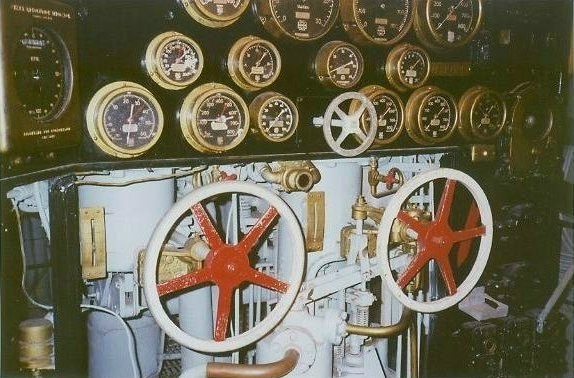
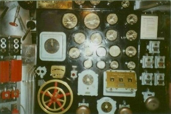
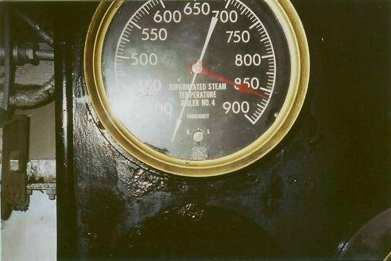
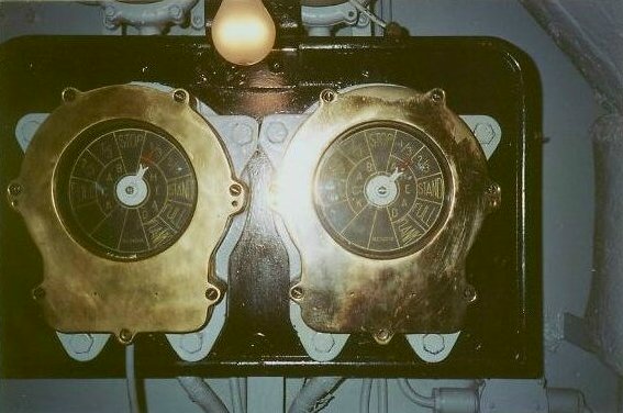
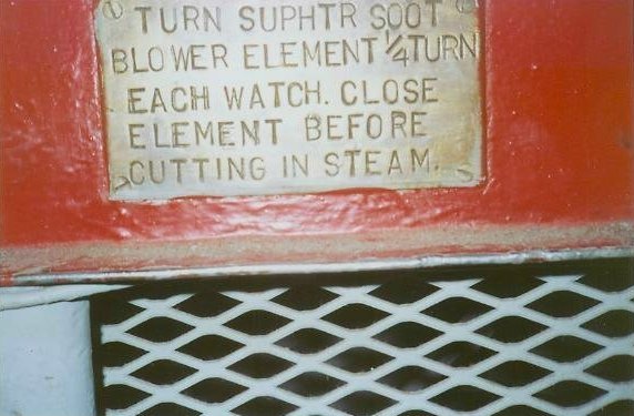
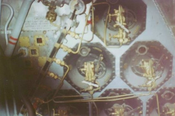
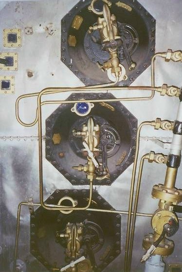
Boiler firing / operating control station. The black gauge panel monitors boiler and fireroom conditions. The large red-and-white handwheels are most likely the boiler firing controls — air registers and dampers, or fuel and steam control valves.The control board, second view. Multiple pressure and temperature gauges, switches, and control handles. This is the operator’s station for managing boiler combustion and steam conditions.Main steam pressure gauge. Scaled 0–800 psi and reading in the 550–600 psi range — consistent with a naval 600 psi steam plant.Superheated steam temperature pyrometer — Boiler No. 4. The dial is marked “Superheated Steam Temperature,” scaled roughly 450–900°F.Engine order telegraph repeaters. A pair of engine order indicators showing the bridge’s orders to the engine room or fireroom. The visible sectors include ahead, astern, stop, and standby.Superheater soot blower instruction plate. “SUPHTR” means superheater. Soot blowers used steam to blow soot off the boiler and superheater tubes.Boiler burner front. Multiple oil burner / atomizer fittings and their associated piping. This is where fuel oil and atomizing steam or air entered the furnace.Burner assemblies, closer view. A vertical view of several fuel-oil burner assemblies and burner registers on the boiler front. The small lines are most likely fuel oil, atomizing steam, and control piping.No. 1 Boiler — wider front view. The label at left appears to read “No. 1 Boiler.” Wider boiler front view showing top burner on saturated side and higher exposing another burner used for creating a smoke screen