
A. Antisubmarine Warfare
14A1. Introduction
Antisubmarine warfare (ASW) comprises the employment of available weapons, resources, and necessary tactics against enemy submarines, their operating bases, and their supporting activities. The purpose of ASW is to deprive the enemy of effective use of his submarines.
Operations contributing to accomplishment of this purpose are various in nature and may be either offensive or defensive in character. In general, the principal categories of antisubmarine operations are as follows:
1. Bombing and mining. Destructive bombing (or bombardment) of enemy submarine pens, bases, building yards, and repair facilities will reduce enemy capabilities to wage submarine warfare. Mining serves the purpose of preventing movement of enemy submarines to and from their bases. Such operations may be carried out by aircraft or submarines.
2. Hunter-killer operations. A hunter-killer group consists characteristically of an aircraft carrier with radar-equipped antisubmarine planes, sonar-equipped antisubmarine helicopters, and a screen of destroyers. Aircraft conduct both surface and undersea searches, and are capable of rocket, depth bomb, depth charge, and antisubmarine torpedo attacks. When aircraft cannot complete the destruction of the submarine, they guide surface units to the scene for concentrated attack and reattack.
3. Escort of convoy. Escort of convoy, or screening, is usually conducted by antisubmarine surface vessels. Air support may be available at times, and may include surface search by fixed-wing A/S planes, or sonar search by helicopters and airships.
4. Harbor defense. Harbor defense comprises measures for protecting fixed geographical areas by preventing penetration of submarines, small surface craft, or manned torpedoes into these areas. Harbor defense measures include using defensive minefields, nets and booms, and underwater listening and echo ranging equipment. Fixed installations are usually supplemented by surface A/S units capable of attacking any submarine detected. Air patrols, including planes equipped with magnetic airborne detection (MAD) equipment, are also available to harbor defense forces.
5. Submarine antisubmarine operations. Submarine-versus-submarine operations are showing increasing effectiveness, and development in this field is being actively prosecuted.
14A2. General
The importance of antisubmarine warfare cannot be too highly stressed. Recent advances have been made in submarine design and operation, such as greater speed and the ability to stay submerged almost indefinitely. These facts, plus the submarine potential of any prospective enemy, make it obvious that maximum effort must be devoted to attain proficiency in antisubmarine warfare. Current emphasis in research and development—in both equipment and tactics—and an intensive fleet A/S training program are directed toward this end.
It was demonstrated during World War II, and has been further confirmed by operational evaluation since that time, that the air-surface hunter-killer team is one of the most effective forces in combating submarines. Aircraft have the advantage of searching large areas quickly, an important consideration because of increased submerged speeds of modern submarines. Formerly, aircraft contact with underseas craft was limited to surfaced or snorkeling submarines. If the submarine submerged before the attack, surface units were guided to the scene for further operations. It is now possible for airborne units to maintain contact on submerged targets and to deliver lethal attacks while the submarine is below the surface.
Airships and helicopters track submarines with sonar. The airship tows a sonar transducer which gives azimuth, or scanning, presentation comparable to surface ship sonar. As a matter of fact, airship sonar applications are quite similar to those of surface vessels, and the airship has the additional advantage of greater search speeds. Antisubmarine helicopters are equipped with dipping sonar. The helicopter hovers in the target area, lowering a searchlight-type sonar transducer for careful step-by-step underwater search.
Another means of tracking submerged targets from the air is by magnetic airborne detection equipment. MAD operates on the same principles as fixed magnetic loops that are standard equipment in harbor defense detection systems. MAD measures distortion of the earth’s magnetic field caused by the presence of ferrous metal such as a submarine.
Attack capabilities of both airships and helicopters have been increased by recent developments. The helicopter is capable of carrying an antisubmarine torpedo, while the airship may attack by torpedo, depth charge, depth bomb, or conventional hedgehogs.
14A3. Weapons
Since antisubmarine warfare has a high priority, the near future will see in use against submarines weapons which cannot be described in this volume because of security classification. In addition to those weapons described in preceding chapters, there is a special group of weapons designed especially for use against submerged submarines. They have common characteristics of sinking or diving from the surface of the water and producing an underwater explosion either (1) on contact with the submarine, (2) in proximity to the submarine, or (3) at a preset depth. Depending upon the launching method, such weapons are grouped as follows:
1. Throwing weapons, including the hedgehog and an antisubmarine rocket called weapon A;
2. Torpedoes;
3. Depth charges;
4. Depth bombs.
In addition to the three classes of active weapons, this chapter includes a discussion of nets and booms, described above as one of the passive means for antisubmarine (and antitorpedo) defense.
B. Depth Charges
14B1. General
Depth charges are thin-walled containers filled with a heavy charge of explosive and designed to explode at a predetermined depth or by the action of an influence fuze.
The older depth charges are cylindrical in shape, about 28 inches long and 18 inches in diameter. They contain 300 pounds of TNT. This type of depth charge, the Mark 6, is now used largely for training. An even larger cylindrical depth charge, the obsolete Mark 7, contained 600 pounds of TNT. The later types of depth charges, Mark 9 and Mark 14, have a teardrop shape and a weighted nose, to increase the sinking rate and improve the underwater trajectory. They contain about 200 pounds of TNT or of HBX and have the same over-all dimensions as the 300-pound cylindrical charge. Representative depth charges are shown in figure 14B1.

The depth at which explosion will occur is controlled in the older type by setting a hydrostatic exploder mechanism which is graduated to 600 or 1,000 feet (in different mods). In the newer charges explosion is initiated by an influence-type firing mechanism. Neither type of exploder mechanism depends upon contact with a submarine. It is extremely difficult to obtain a direct hit with depth charges, because the exact position of the submarine usually is not known. Consequently, depth charges depend on the percussive wave of the explosion for their effectiveness.
The effective radius of the percussive wave depends upon the structural strength of the attacked vessel, and no definite values can be stated. Approximate information indicates that a 600-pound charge may cause moderate damage at 80 feet, but to be fatal it must explode within about 30 feet. The 300-pound charge may prove fatal within 20 feet. It is to be noted that doubling the weight of charge does not double the effective radius.
Destroyers, destroyer escorts, subchasers, PT boats, and other vessels likely to engage submarines, carry depth charges. Generally several charges are released in rapid succession to form a pattern in depth, width, and length, and thus increase the probability of destroying the submarine. The pattern is obtained by dropping some charges from release gear on the stern, and firing others abeam from projectors, with appropriate depth settings made on the depth charges before launching. The charges are never thrown far from the attacking vessel; hence care must be taken that the ship is making sufficient speed to be out of the way of the violent effect produced. The computation of the speed necessary is considered to be part of the antisubmarine fire control problem, which is discussed in volume 2.
14B2. Release gear
One type of track used to drop depth charges from the stern of a vessel is illustrated in figure 14B2. Essentially, it consists of inclined rails on which the charges rest, with suitable mechanical devices arranged to release one charge at a time. The track shown will hold eight Mark 6 charges. Minor modifications make the track suitable for dropping teardrop charges.
The charges roll aft by their own weight and rest against the after detents. When the release lever is operated, the after detents depress, allowing the first charge to roll off the track into the water. At the same time, forward detents (not shown) rise and hold the second and following charges steady on the rails. When the track control lever is returned to its original position, the detents move in reverse directions, and the second charge rolls down to the dropping position against the after detents. The track control unit is connected hydraulically to a control unit on the bridge of the ship by means of which the charges may also be released.
Most depth-charge release tracks bear mark and mod designations. Four tracks, however, have letter designations instead. All four of these tracks are intended primarily for use on small vessels and motor boats, although they have been grouped along the sides of somewhat larger craft on occasion. All have cable pendants for holding the depth charge (or pair of charges) in place. All have built-in local control devices. Types A and C hold a single charge; types B and D are designed to hold two charges. They are dropped by releasing the cables which hold the case in position and letting the charge roll from the track.

14B3. Projectors
The Depth Charge Projector Mark 6 Mod 1, commonly called the K-gun, is illustrated in figure 14B3. It is used to launch the 300-pound cylindrical depth charge or the 200-pound teardrop charge.
The K-gun consists of a smooth-bore barrel attached to an expansion chamber fitted with a breech mechanism. The breech plug is an interrupted-screw type, housing a firing mechanism which provides for local percussion firing by lanyard, or electrical firing controlled from the bridge.
The projector is permanently secured to the ship, and cannot be trained or elevated. Variations in range are obtained by altering the weight of the impulse charges, which are assembled in 3-inch cases similar to those used for torpedo impulse charges. Three standard weights of spherohexagonal black-powder charges are used to obtain ranges of 50, 75, and 120 yards (Mark 6 depth charge), or 60, 90, and 150 yards (Mark 9 and Mark 14 depth charges).
The depth charge is launched with an arbor (fig. 14B3) attached to it, the action of the propellant gas being against the base of the arbor. The arbor used with a cylindrical depth charge remains attached to the charge after firing, whereas that used with a teardrop charge detaches after firing, to permit taking advantage of the streamlined design.
14B4. Depth-charge operation
Mark 6, Mark 7, and Mark 9 charges are similar in functional operation. The general arrangement of a typical charge is shown in figure 14B4. The principal components are:
1. The main charge and case. The outer shell is a sheet-metal case, through which passes a central tube. The space between the tube and case is completely filled with cast TNT or HBX.
2. The booster and booster extender. The booster is attached to the booster extender, and is free to move longitudinally in the tube. A central recess in the inboard end of the booster envelops the detonator when the booster is moved against the centering flange. The booster extender, operated by hydrostatic pressure, pushes the booster against the centering flange when the charge reaches a depth of between 11 feet and 25 feet.
3. The detonator and pistol. The detonator is secured to the inner end of the pistol, and is supported in the center of the tube by the centering flange. The pistol mechanism, when operated by hydrostatic pressure, releases a firing pin which strikes the cap of the detonator. Before the charge is launched, the depth at which the pistol is to operate is set as described in the next article. Depth settings from 30 to 1,000 feet may be made.
Accidental detonation of the depth charge is prevented (1) by setting the pistol on SAFE, thereby locking the pistol, and (2) by a safety fork, which prevents the booster from moving inward. The booster will not detonate unless it partially surrounds the detonator. An inlet-valve cover protects the water inlets to the pistol against dirt. It should always be removed prior to firing, as otherwise it will prevent the entrance of water after a charge is launched.
Depth settings are made with a special wrench. If the charge is dropped from a rack, the safety fork and inlet-valve cover are automatically wiped off by wiping plates on the rack. The cover must be removed by hand and the fork by lanyard if the charge is launched from a projector.

14B5. Pistol operation
The construction of a pistol is illustrated in figure 14B6. The firing pin is secured to the firing plunger. Around the plunger are three holes, each of which contains a lock ball. The release plunger is free to slide within the firing plunger, and is held by a spring in the position shown. The lock balls, held outward by the release plunger, rest against the end of the guide-tube bushing and prevent the firing plunger from moving toward the detonator.
When water flows through the inlet, it fills the bellows. Water pressure then expands the bellows, pushing the piston and piston stem toward the release plunger. This action compresses the depth spring and the firing spring. As the movement continues, the piston stem contacts the release plunger and moves it toward the firing pin. When the annular recess on the release plunger has moved under the lock balls, the latter move inward, releasing the firing plunger with its attached firing pin, which is driven into the detonator by the firing spring.
The depth spring is seated in the adjusting bushing, and is compressed between it and the spring collar as the bellows expand. The adjusting bushing, threaded within the depth-setting sleeve and keyed to the piston stem, is positioned by rotation of the sleeve when the index plate is turned. The position of the bushing controls the resistance offered by the depth spring to the expansion of the bellows, and thus determines the water pressure required to operate the pistol. When the pistol is set on SAFE, the adjusting bushing is so close to the spring collar that the piston stem is prevented from moving far enough to release the locking balls.
The 300-foot setting uses the maximum strength of the depth spring; hence it cannot keep the pistol from firing at greater depths. The inlet valve provides the necessary control for depths between 300 and 1,000 feet. The valve ball is held against its seat by the valve spring. The compression of this spring is set by rotating the adjusting sleeve (with the inlet-valve cover off). When the valve is set for depths between 0 and 300 feet, it admits water freely as soon as the charge is submerged. When set for greater depths, the valve admits no water until the set depth is reached. Then the pressure of the water opens the valve, and the water pressure immediately expands the bellows, firing the detonator. Figure 14B5 shows the two dials.

For depths up to 300 feet, the deep-firing pointer on the adjusting sleeve is set at 0 to 300, and the index pointer on the index plate is set to the required depth. The dial plate has, opposite each depth mark, a small recess to receive the index-pointer plunger, which acts as a detent to maintain the setting. For depths greater than 300 feet, the index pointer is set at 100, and the depth-firing pointer is set to the required depth.
A booster-extender mechanism, ready for launching, is shown in figure 14B6. The operating parts are enclosed within a watertight bellows, which fills with water and extends the booster to envelop the detonator as the depth charge descends.
The booster and the piston are secured to the spindle, which is locked in position by the safety fork. When the safety fork is removed at launching, the bellows, assembled under slight compression, elongates enough to open the inlet around the spindle. The spindle moves inboard until the outboard shoulder of the annular groove contacts the locking balls held in the locking slide. The spring prevents further inboard movement of the locking slide until the water begins to operate the bellows.
As water pressure builds up, the locking slide is gradually drawn inboard by the spindle. When the charge reaches a depth of between 11 and 25 feet, the locking balls move outward into the enlarged recess in the spindle guide and release the spindle. Water pressure then quickly extends the bellows, placing the detonator envelope around the detonator, thus arming the charge.

14B7. The Depth Charge Mark 14
The Depth Charge Mark 14 (see fig. 14B7) is a streamlined missile similar to the Mark 9, but is fitted with an influence-type firing mechanism. This device greatly increases the accuracy with which the explosion may be placed in depth, and eliminates the disturbance caused by explosions of noneffective charges, which otherwise may interfere with the solution of the antisubmarine fire control problem.
The case, like that of the Mark 9, contains a 40-pound nose weight, and has canted fins which provide stable underwater flight characteristics, and a sinking speed of about 23 feet per second. These charges are launched in a conventional manner from tracks or projectors, but because of the influence feature, they do not have to be set for a depth pattern.
The A-4 is an influence firing mechanism, designed to initiate an explosion when the charge is close enough to a submarine to do serious damage. Delay in its operation and in the detonator make the minimum depth at which the charge will fire upon actuation from a normal signal about 65 feet. It is equipped with an anticountermining switch which prevents firing for a short period following any other explosion near by. The mechanism may fire upon reaching the bottom of the ocean or, in very deep water, the charge may fire at about 2,500 feet as a result of leakage or deformation of the case.
The Pistol Mark 12 acts as a safety device. It is equipped with two hydrostatic arming switches, a detonator, and a detonator positioning device. Prior to use, the pistol safety latch is kept at SAFE and locked with a safety fork. When the charge is to be used, the safety latch is turned to SERVICE or to the deep arming position, and the safety fork is removed by lanyard or by wiping. Water pressure arms the pistol at a depth of about 35 feet when set on SERVICE. When the deep-arming safety latch is set to the deep-arming position, it locks the extender mechanism and keeps the pistol from arming until some depth between 200 and 400 feet is reached.
The deep-arming feature is designed for use in “creeping attacks” against deeply submerged submarines. It prevents premature explosion which might result in damage to a slowly moving attacking vessel.
C. Depth Bombs
14C1. Description
Figure 14C1 shows a current depth bomb, the HBX-loaded Mark 54 Mod 1. Depth bombs are sometimes defined as depth charges designed for dropping from aircraft.
Depth bombs were among the major antisubmarine weapons used in World War II. Three methods of dropping—toss bombing, glide bombing, and low-altitude release—were employed.
A depth bomb has a rather light case. The explosive filler comprises about 70 percent of the weight of the assembled bomb. To reduce the danger of ricochets at small entrance angles, the depth bomb has a flat nose. Fuzing arrangements are discussed in the next article.

14C2. Fuzing
When carried in aircraft with selective arming, depth bombs normally take two fuzes. An impact-type nose fuze with a special flat arming vane is installed for use against suitable surface or land targets. A hydrostatic tail fuze, shown in figure 14C2, is intended for use against submerged submarines.
When the tail fuze is dropped armed, the nose fuze must be dropped safe. Otherwise the bomb will detonate on water entry. In planes that lack selective arming, only the tail fuze is used.
During World War II, many depth bombs were fitted with an athwartship hydrostatic fuze. This feature, however, is not present in the Depth Bomb Mark 54 Mod 1 shown in figure 14C1.
The tail fuze shown in figure 14C2 allows five choices of depth setting, varying from 25 to 125 feet. Normally the depth setting is made before take-off, though it can be made aboard the plane. This gives an approximate control over the depth of the explosion.

14C3. Damage to target
Like its close relative the depth charge, a depth bomb is unlikely to hit a submarine directly. Instead, it gains its effect by creating an underwater pressure wave that may weaken or crush the hull plates of the target.
D. Throwing Weapons
14D1. The 7.2-inch rocket
Chapter 11 described the solid-nose 3.5-inch rocket, which is used as an airborne antisubmarine weapon. Surface craft may also carry antisubmarine rockets and rocket-type missiles.
The first thrown missile put in service by the Navy was the 7.2-inch rocket and its associated Rocket Launcher Mark 20, illustrated in figure 14D1. Two such launchers, mounted on the forecastle of an antisubmarine vessel, can fire a pattern of eight charges. Since the charge is a true rocket, there is negligible thrust against the deck when a pattern is fired; thus this weapon is suitable for use on such small craft as PC’s and SC’s.
As the rocket head carries a contact fuze, a direct hit on the target submarine is required; but, when a direct hit is obtained, even the small charge carried in the rocket head can well be lethal.
The Mark 20 launcher and its associated rockets have been replaced in service on DE’s and larger vessels by the Mark 10 projector and its 7.2-inch missile. Since, however, the Mark 10 projector is much heavier than a rocket launcher and the deck thrust incident to its use is considerable, the Mark 20 rocket launcher is not considered obsolete for small craft.

14D2. 7.2-inch projector charge
The projector charge is similar in shape to the 7.2-inch rocket. It has a head 7.2 inches in diameter, with a tail, fins, and a shroud. (See fig. 14D2.) However, this missile is not a rocket; the propelling charge is an impulse charge of smokeless powder. The fuze arms during flight and is designed to function upon impact only. The explosive charge consists of 30 pounds of TNT. The tail is a steel tube, the forward end of which contains a cartridge case with the propelling charge of smokeless powder. The propelling charge is fired electrically by means of a primer in the base of the cartridge case. As the missile leaves the projector, the cartridge case base falls to the deck.

14D3. The 7.2-inch projector Mark 10 and Mark 11
Several different projectors are used with the 7.2-inch charge. In principle, all of them resemble the Mark 10 (fig. 14D4), which projects a pattern of 24 charges ahead of the attacking vessel. The missiles are loaded on cylindrical bars called spigots, attached to cradles which can be swung about a fore-and-aft axis by means of a roll-correction gear assembly mounted on a gun-train indicator pedestal. This movement is limited, but it allows the spigots to train enough to compensate for roll of the ship and to aid in leading the target. The spigots are so positioned that, when fired, the charges describe an elliptical pattern of about 140 by 120 feet.
The base frame of the projector consists of two 18-inch channel beams running fore and aft and two 12-inch I-beams athwartship, forming a box. Each I-beam carries four bearings which support the cradle assemblies. The four 10-inch cradle beams (fig. 14D5) ride on trunnion assemblies welded at each end. The trunnions fit into the bearings on the base frame. The cradles can be tilted on their trunnions about an axis parallel to the keel of the ship. A connecting bar tilts all four cradles simultaneously when the roll-correction gear is operated.
Six spigot sockets are welded to each cradle and hold the spigots on which the charges are loaded for firing. The wires of the firing circuit pass through holes in the spigot, as shown in figure 14D3. The ungrounded side of the firing circuit terminates in a firing pin, which is contained in the spigot. The grounded return of the firing circuit is through a spring contact which touches the inside of the projector-charge tail tube.

14D4. Operation
The projector is loaded by placing the tails of the missiles over the spigots and sliding them down gently. After the missile is all the way down on the spigot, it is rotated 360° to ensure good contact between the firing pin and primer. (See fig. 14D6.)


The charges are fired by means of a ripple switch. This switch has 12 contacts and, as the switch rotates, it completes the firing circuit to the missiles by pairs. The interval between contacts is about 0.10 second (0.20 second in some mods). The firing circuits are so wired that the missiles with the highest trajectories are fired first and those with the flattest trajectories last. Thus all the missiles hit the water at approximately the same time. The average range is about 200 yards. Variations in powder temperature have little effect between 30° and 90° Fahrenheit. Figure 14D7 shows the nominal trajectory and sinking time of the 7.2-inch projector charge.
The Mark 11 projector is very similar to the Mark 10 described above.

14D5. The 7.2-inch Projector Mark 15
In principle of operation and in general external appearance, the A/S 7.2-inch Projector Mark 15 (fig. 14D8) resembles the Mark 10 type described in some detail in the preceding articles. It is equipped with 24 spigots which accept 7.2-inch charges like those already described, and ripple-fires them in a circular pattern. However, the cradles on which the spigots rest are at right angles to the line of fire (the Mark 10’s are parallel to the line of fire), and can rotate in limited arcs of elevation in trunnion bearings. (The Mark 10 projector’s spigots cannot move in elevation at all.) The cradles are cross-connected so that they elevate in unison. The cradles are housed in a trainable carriage mounted on a stand on the deck (as contrasted with Mark 10’s fixed-base frame). The elevating and training parts are positioned by electrohydraulic power drives similar to those used on 40-mm quad mounts.
E. Nets and Booms
14E1. General
Efforts to block the entrances to harbors against surface vessels date back to the earliest times. The appearance of the high-powered, steel-hulled surface vessel, the submarine, and the torpedo have made the present-day problem of protecting ships at anchor increasingly difficult. The problem has evolved into one of defense against torpedoes. This defense is accomplished in two ways: by preventing the vessel carrying the torpedo from approaching within firing range, or by stopping the torpedo itself. See figure 14E1.

There are five classes of nets and booms, with individual variations within each type. These are:
1. Type S net (antisubmarine).
2. Type I (Indicator) net (antisubmarine).
3. Type T net (antitorpedo).
4. Type B boom (antimotorboat).
5. Rigid obstructions.
To protect ships at anchor in a harbor either (1) the harbor must be blocked off or (2) each ship must be protected individually. During World War II merely blocking off the harbor did not, in itself, give sufficient protection, because of the torpedo-carrying aircraft. Therefore, valuable ships and floating dry docks may be surrounded by a variation of the Type T net called an ISP (Individual Ship Protection) net.
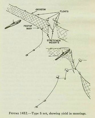
14E2. Type S net (antisubmarine)
The purpose of the Type S net is to block submarine attacks, or, if a submarine does break through, to reveal its presence to patrol craft. To prevent the passage of a submarine the net must be constructed of very heavy material and must have sufficient elasticity to absorb a sudden heavy strain without breaking. The three basic elements are:
1. The net, a fabric woven of heavy wire.
2. The flotation, a system of buoys and floats.
3. The moorings, the anchors and their connections.
The standard submarine net is constructed of a diagonal mesh measuring 8 feet per side, assembled in lengths, called panels, which measure 300 feet. Nets are tailored to fit the depth of the water; they must reach the bottom without fouling on it. Two panels joined together longitudinally form a section, the lineal unit used in installing and when referring to large net systems. The net is woven around a top wire rope, called the jackstay, and around end and bottom wire ropes, called perimeter ropes. The jackstay supports the weight of the net, and it is to this that the flotation gear is secured.
The net is floated by spherical or barrel-shaped buoys shackled to the jackstay. The moorings are designed both to keep the net in position against the force of tide and current, and to furnish the installation with the required elasticity. The typical mooring consists of four 6,000-pound stockless anchors, two on the seaward and two on the harbor side of the net. These anchors are laid in tandem at right angles to the net line. Elasticity is provided by slinging heavy iron cubes, called stretcher weights, in the bights of the mooring system. The stretcher weights and ends of the net are floated as illustrated in figure 14E2.
A harbor entrance net has one detachable panel, called a gate, which may be swung open by a gate vessel to allow passage of friendly ships. In deep entrance channels the gate may be guarded by a submerged bottom net under the entrance. Such a net is supported by submerged buoys; it effectively seals the gate against submarines attempting to slip through, deeply submerged, while the gate is open. Of course the top of this net must be deeper than the draft of the largest friendly ship which will use the gate.
14E3. Type I (Indicator) net (antisubmarine)
The purpose of this net is to indicate the position and movements of a submerged submarine. As the Type S net is extremely heavy and bulky, it requires heavy equipment to move it, lay it, and tend it. Therefore a relatively light, compact net, easily shipped to and installed in distant harbors, is required.
The Type I net is not designed to stop a submarine. Its strength requirements are that it must be capable of staying in position in all conditions of wind and weather, and that any section must hold together while being towed by a submerged submarine.
The net is woven with a 4-foot diagonal mesh into panels 210 feet long and 50 feet deep. The net is not tailored to fit the depth of water, but the panels are fastened to each other until the net reaches the bottom. Any excess is secured by brailing and stopping, so that it will not foul on the bottom.
The two distinctive features of the Type I net are burster clevises and the indicator floats. Burster clevises are U-shaped shackles used to connect the mesh of the net to the jackstay. They are designed to break at a predetermined stress, thus freeing the net from the jackstay. Indicator floats are small steel pontoons, each containing a reel with 300 feet of line, a flotation chamber, and a pot of calcium chloride and calcium phosphide. When a panel of the net is pulled clear of the jackstay, tear-off strips are pulled from the indicator floats; water enters the pots containing the calcium compounds, and smoke is generated.
The operation of the net is illustrated in figure 14E3. A submarine, attempting to enter the harbor, comes in contact with a panel of the net; when the stress on the net reaches a certain amount the burster clevises part, freeing the panel from the jackstay; this panel drapes itself around the bow of the submarine; as the net moves away with the submarine, the indicator floats initially remain attached to the jackstay; the tear-off strips are pulled clear and the floats produce smoke; when the 300 feet of line in the indicator float is paid out, the floats are pulled clear of the jackstay and are towed along the surface astern of the submarine.

14E4. Type T net (antitorpedo)
The Type T net is used (fig. 14E4) to fence out torpedoes. It may be laid in any of the following ways:
1. As a continuous barrier across a harbor.
2. In a non-continuous baffle arrangement.
3. In individual ship-protection units.
The Type S net must withstand the impact of the slow-moving large body of a submarine, the kinetic energy of which is diffused rapidly throughout a large area of the net. A torpedo, however, poses an entirely different problem to the net designer. A torpedo arrives at the net with a high degree of kinetic energy. At the critical instant of impact, because of the small diameter of the warhead nose and its high velocity, that total energy of the 300-horsepower torpedo is concentrated upon one element of the net. If that element fails, the net is defeated.
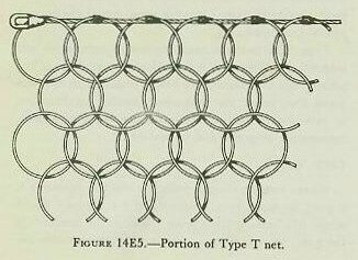
The distinctive feature of the torpedo net is the grommet. Grommets are rings of steel wire with a breaking strain of 46 tons. As the net is woven, each grommet finally is passed through six other grommets (as shown in fig. 14E5), producing a fabric much like the chain-mail armor of feudal days. When the torpedo strikes, the force of its impact is expended in stretching, or elongating, the grommets, each one rendering against the adjoining grommets.
Antitorpedo nets are attached both to the top and to the bottom of the flotation buoys, in order to protect against surface torpedo runs. The bottom of the torpedo net is left free to swing from the jackstay, thereby adding to its elasticity.
The continuous barrier and the baffle methods of laying the Type T net are self-explanatory. However, neither of these affords protection against torpedo attack by plane.
An Individual Ship Protection (ISP) net provides an answer for this problem. It is an antitorpedo net completely surrounding an individual ship. The net is held off about 60 feet from the sides of the ship by special spars and is attached to the anchor chain or mooring buoy. The main disadvantage of this net is tactical; that is, it interferes with the ability of a ship to get under way rapidly.

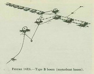
14E5. Type B boom (antimotorboat)
The purpose of the boom is to block passage of motor torpedo boats. Such a craft is built with an extremely light hull, because speed is its principal and virtually its sole protection. The Type B boom is designed with this weakness in mind.
The distinctive feature of this boom is the baulk—a heavy iron-strapped wood-and-metal tank fitted with eyebolts and links for connecting it to the boom jackstays. Two watertight iron tanks occupy the interior of each baulk and provide flotation. Each baulk is fitted with four steel spike cutters whose points project outward from the baulk. The baulks are connected by upper and lower jackstays; along the upper jackstays, at intervals of 4 feet, are four-pronged steel star cutters.
While this type of defense has been effective under favorable conditions, its limitations should be kept in mind. It is designed only for protection against very light craft and will not stop steel-hulled boats and heavier landing craft equipped with propeller guards.
Moreover, the weight and shape of the baulks creates a definite problem where strong currents are encountered.
14E6. Rigid obstructions
It is sometimes necessary to close entrances to harbors where the water is too shallow for efficient net operation. In such cases it is usually more efficient to employ some kind of rigid obstruction. These may take one of several forms:
1. Cribs. These are heavy structures built up from the bottom in the form of boxes of the heaviest timbers available and ballasted with rock or concrete. Heavy wire is rigged between them.
2. Concrete blocks. Where time and cost are not controlling factors, heavy tetrahedral concrete blocks have been cast with their bases jointed to form a semibreakwater across the channel.
3. Dolphins. Pile dolphins may be used where the nature of the bottom and availability of pile-driving equipment permit. These may be connected with jackstays and star cutters.
4. Blockships. The traditional means of closing a harbor is, of course, to sink a ship in the channel. This is very difficult to do correctly since, to be effective, the ship must be sunk on an even keel directly across the channel. Provisions should be made for very rapid, controlled flooding and for venting of trapped air.
14E7. Multiple installations
Because of the specialized character of nets and booms no single installation can deal with all of the torpedo threats which may develop against an important base or anchorage. Often it is necessary to combine different types of barriers, either using one in support of another, or joining two or more into a single-line obstruction.
A Type S net, for example, constitutes no very effective obstacle to a torpedo fired through its mesh. And to a motorboat designed to ride over low obstacles a torpedo net would not be a much more positive barrier than a motorboat boom would be to a torpedo fired under it.
Sometimes the only solution is a combination of two or more types of defense. In practice any or all of the possible combinations may be used, from simply doubling a line of one kind of net to combinations of three separate types. Standard Type S moorings for a double line will readily carry a Type T net in place of the second Type S net. Such a barrier, while not as formidable to either a submarine or a torpedo as a double line of its specific antidote, will still stop most torpedoes fired into it and, if well patrolled, will leave little chance that a submarine will pass through undetected. This combination is a compromise, but a thoroughly practical compromise. Without unlimited reserves of material it often constitutes all that can be done in a given situation.
The double-line Type S net installation provides as nearly complete protection against submarines as can be established at the existing stage of net development. But a review of actual war experience in this field indicates that, when considered on the basis of calculated risk, the expense in materials and transportation capacity is justified only where there is both very great risk of determined attack by submarines and an extremely important prize inviting such attack.
The case against double-line installation applies in a lesser degree to torpedo nets. They too, with their flotation and moorings, impose a heavy load upon war-burdened transportation and maintenance facilities. Torpedo net is used in greater quantities than any other type of heavy installation. A practice which would double the mileage of net required would almost inevitably entail leaving some naval anchorages entirely unprotected.
Type SBT net is a combination of submarine and torpedo net lines with a motorboat boom (fig. 14E6) added, the submarine net being installed at the seaward line, using the motorboat baulks for flotation. It provides protection against three types of attack: submarine, torpedo, and motorboat.
14E8. Gates
Where nets or booms entirely close the entrance to a port, passage must be provided for friendly vessels while still barring the enemy. This is the function of the gate. Net and boom gates are simply movable sections of the barrier so rigged that they may be opened to permit the passage of friendly craft. When closed, such gates will be as strong as or stronger than the other sections of the barrier.
Gates are classified according to use as main, emergency, and side. All must be so rigged that they may be operated easily and rapidly under all conditions of weather and sea, will be entirely secure when closed, and will be controllable by the officers operating the port’s defenses.
They are classified according to design as horizontal and vertical. The horizontal gate is operated by swinging it open, still floated by its buoys, until the passage is cleared. The vertical gate is lowered at one end or at both ends until sufficiently submerged to permit vessels to pass over it.
14E9. Summary of net defenses
In considering the type of net defenses to employ, one must give thought to transportation facilities, weight of the net and accessories, net-laying and tending vessels available, and tactical requirements. Type S and Type T nets are very heavy and bulky, and require the use of large laying and tending vessels. The Type I nets are made in various weights, varying from fairly heavy to extremely light.
The adage among net personnel states that “a net is no stronger than its patrol.” These patrols must keep watch not only for the enemy but also for damage to the net by currents, weather, and corrosion. The most important factor in maintaining effectiveness of any net installation is a continuous and alert patrol.