
Chapter 13: A. General • B. Aircraft Mines • C. Mine Warfare
13B1. Aircraft Minelaying
Almost any aircraft capable of carrying bombs can also carry and lay mines. Aircraft were used extensively for this purpose during World War II, carrying and releasing some mines from ordinary bomb racks or shackles, and other mines from cables suspended between a pair of racks or shackles. An aircraft mine may either be free-falling with fin stabilization, or may employ a parachute to control the rate of fall.
As a minelayer, the aircraft has several advantages. Planes can lay mines in shallow bodies of water, including rivers, which cannot be penetrated by submarines or the larger surface minelayers. Planes can also drop additional mines to replenish a mine field without encountering the hazard of detonating mines previously planted. Mines dropped by parachute can be released from relatively high altitudes, although with some loss of accuracy. On the other hand, minelaying operations involving parachutes are subject to detection by the enemy.
13B2. Typical Aircraft-Laid Mine
Figure 13B1 shows a current aircraft mine: Mod 9 of the Mark 10 type of magnetic dip-needle mine.
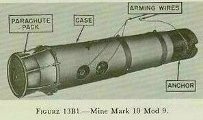
Unlike many aircraft-laid mines, the Mark 10 Mod 9 is a moored rather than a bottom type — which explains the presence of an anchor. There are two other current modifications of the Mark 10 magnetic mine. Mod 3 is laid from submarines and Mod 7 from surface craft. As regards the anchor and the interior arrangement of the case assembly, the Mod 9 resembles both of these modifications. Its differences lie in the parachute assembly and in the other external provisions for aircraft planting.
Parachute Assembly
Two parachute assemblies are authorized for use with Mine Mark 10 Mod 9. One, Parachute Pack Mark 14 Mod 1, is shown in figure 13B1. The other, Parachute Pack Mark 3 Mod 0, is shown in figure 13B2.
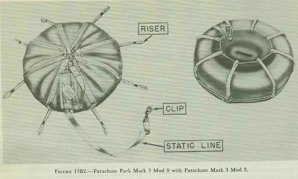
The Mark 3 Mod 0 pack has a plastic dish that fits the contour of the end of the mine case, to which it is bolted. The folded parachute lies inside the dish. The cover is made of canvas, with eight sectors or flaps. The risers shown in figure 13B2 attach the parachute and the pack to the release mechanism.
The static line keeps the parachute from opening dangerously close to the planting aircraft. One end of this line is attached securely to the planting craft. The other end is attached by break cord to the parachute. When the mine has fallen the length of the static line, the line acts to pull the parachute from the dish. Almost at the same instant, the break cord snaps and frees the parachute from the static line.
Parachute packs of more recent design have been improved in various details, but are similar to the Mark 3 Mod 0 in both components and principles of operation.
Release Mechanism
The device shown in figure 13B3 serves a double purpose. Until the mine enters the water, the release mechanism secures the parachute to the mine. Upon striking the surface of the water with great force, the 2 impact plates pull out the release pins that have been holding the 2 halves of the release mechanism together. Flat springs, assembled between the release mechanism and the mine case, then force the 2 halves apart and let the mine sink free of the parachute.
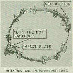
If the parachute remained with the mine after water entry, it could foul the mine mechanisms — or might even roll or drag the mine in such a way as to cause premature explosion.
Arming Wires
Like bombs, aircraft mines are assembled with arming wires (shown in figure 13B1). These wires, threaded through the delay devices, keep those devices in their unarmed condition. The bitter ends of the wires are attached to the planting aircraft.
To release the mine ready for arming, the bombardier operates his controls to pull the wires from the mine at the instant of planting. To jettison the mine in a comparatively safe condition, he lets the wires fall with the mine.
A jettisoned mine, however, is not absolutely safe. Therefore the area where it was dropped must be noted with care. As soon as practicable after a mine has been jettisoned over a friendly area, trained personnel are sent to dispose of it.
Fairings
Some mines are assembled with fairings — attachments designed to improve the streamlining of the case and thus make the trajectory easier to predict.
← A. General • Continue reading: C. Mine Warfare →