↩ Naval Ordnance, 1937 — Full Table of Contents
Historical Development
1201. Historical development
The first publicly recorded proposal to sheath the hulls of naval vessels with a metal shield was made by Sir William Congreve in The Times in London on February 20, 1805. A similar proposal was later made by John Stevens, of Hoboken, New Jersey, in 1812. Nothing came of these proposals for years, but in spite of such lack of encouragement, John Stevens and his sons undertook a series of experiments by which they determined the laws of penetration of iron plates by cannon balls and the maximum thickness of iron plate necessary to defeat any known gun. In 1842, Robert L. Stevens, one of John Stevens' sons, presented the results of these experiments, and a new design of a floating battery, to a committee of Congress. These experiments of Stevens aroused great interest both in America and Europe. In 1814 a Frenchman, General Paixhan, had also pointed out the necessity of armoring ships, and in 1845 Dupuy de Lome designed an armored frigate for the French government. These proposals resulted in the laying of the keel of the armored Stevens Battery in Hoboken in the spring of 1854, followed in a few months by four keels in Toulon, and but a few months later by three more in England. One of the French floating batteries was fittingly named the Congreve. During the following year occurred the first engagement in which armored vessels participated—the bombardment of the Kinburn forts in the Crimean War by three of the French batteries.
1202. Iron armor
The only metal, practicable and available in table quantity, at this period, was iron, wrought or cast, and all experiments showed that the wrought iron was far superior, pound for pound, to the cast iron, in defeating projectiles. Wrought iron was therefore adopted for marine use, and these first ironclads were protected by solid plates between 4 and 5 inches thick backed by 36 inches of solid wood timbers.
The most costly experiments were carried out, especially in Europe, where the iron industry was most highly developed, to improve the resisting power of wrought iron armor. Tests were made of laminated plates, with the laminations in contact, and with wooden timbers between, but in all cases, single plates gave greater resistance per pound of protection.
During the Civil War most of the armor employed on American vessels was laminated wrought iron, but this was necessitated by lack of facilities for manufacturing single plates of proper thickness, rather than by any superiority for that type of armor.
Proposals for the production of face-hardened armor were early made. At first these proposals were to face wrought plates with cast or chilled iron plates, but as these schemes involved the same loss of efficiency as was exhibited by laminated plates, and because of the insecurity of the bond between the plates, the hard plate failed to secure the full support of the tough back; they all failed to compare favorably with single iron plates. But as far back as 1863, a Mr. Cotchette proposed, in England, the welding of a 1-inch blister steel plate to a 3-inch wrought iron plate; and later, in 1867, Jacob Reese of Pittsburgh, Pa., patented a cementation compound which he stated could be used for cementing and hardening armor plate. Efforts to carry out these proposals failed for many reasons, primarily because the general development of metallurgy was not equal to the task. It should be remembered that the Bessemer process of making steel in a converter was developed between 1855 and 1860 and that the Siemens-Martin process of making steel in an acid open hearth was developed in France and England a few years later, each process being brought to the United States several years after its European development.
Cast iron has been used for armor in land fortifications, where weight is of slight importance, but as stated above, it has never been applied to naval vessels. The most prominent example of cast iron armor is the famous Gruson turret. These turrets were made of large iron castings, the exterior surfaces of which were chilled by heavy iron chills in the moulds, and were of an oblate-spheroidal shape. Due partly to their shape, but also to the fine quality of the iron and their great thickness, these turrets were considered of great value and were used extensively in protecting European frontiers. The first Gruson turret was tested in 1868 by the Prussian government.
1203. Steel armor
In 1876 gun power and projectile quality had so increased that about 22 inches of iron was necessary to accomplish the defeat of a projectile from the heaviest cannon, but in that year occurred, at Spezia, a trial which revolutionized armor manufacture and permitted a reduction in thickness. In these trials a 22-inch mild steel, oil-quenched plate manufactured by the great French firm of Schneider et Cie. completely outclassed all its iron competitors. This plate is reputed to have contained about .45 per cent carbon and to have been hammered down to the required thickness from an ingot about seven feet high. The process of manufacture was kept secret.
This steel plate, while possessing superior ballistic resistance, was more prone to breaking up and this difficulty led to the next real development, which logically resulted from efforts to combine the hardness of steel in the face of a plate with the toughness of iron in its back. The steel used in these plates was made in Siemens-Martin open-hearth Furnaces.
1204. Compound armor
Thus resulted a new type of armor—the compound type—the two principal examples of which were the Wilson Cammel compound plate in which an open-hearth steel face was cast on top of a hot wrought iron back plate, and the Ellis-Brown compound plate in which a steel face plate was cemented to an iron back plate by pouring molten Bessemer steel between them. In both these processes, which were English, the plates were rolled after compounding. For the next ten years there was no especial development in armor manufacture other than minor improvements in the technique of manufacture, and great competition and controversy existed as to the relative quality of all-steel and compound armor. The all-steel armor was a simple steel of about .30 per cent to .40 per cent carbon, while the steel face of the compound armor contained between .50 per cent and .60 per cent carbon. These two classes of armor, their comparative value depending largely on the skill with which they were made, were approximately 25 per cent superior to their wrought iron predecessor, that is to say—a 10-inch all-steel or compound plate would resist the same striking energy that a 12.6-inch iron plate would withstand.
1205. Nickel-steel armor
The next step in advance occurred about 1889 when Schneider introduced nickel into all-steel armor, and with the advent of nickel-steel armor began the complete elimination of compound armor. The nickel greatly increased the strength and toughness of steel. The amount of nickel in the first few examples of nickel-steel armor varied between 2 per cent and 5 per cent but finally settled down to about 4 per cent. At about this same time oil and water quenching were successfully applied to armor plates by Schneider. After forging under a hammer, and annealing, the plate was heated to a tempering heat and its face was then dipped for a short depth in oil, this tempering being followed by a low temperature anneal. These improvements resulted in a further increase of about 5 per cent in the resistance of armor; that is to say, a 10-inch nickel-steel treated plate equaled about 13 inches of iron.
It was at this stage of development that the manufacture of armor was undertaken in America by the Bethlehem Iron Company, under the supervision of Mr. John Fritz, and shortly afterward by the Carnegie Steel Company, under Schneider patents. The first deliveries of armor for the old Texas, Maine, Oregon, and other ships of that period consisted of heat-treated nickel steel, containing about .20 per cent carbon, .75 per cent manganese, .025 per cent phosphorus and sulphur, and 3.25 per cent nickel.
1206. Harvey armor
In 1890 the next great improvement was begun by the introduction of the Harvey process which was first applied to armor when a Creusot 10.5-inch steel plate was Harveyized at the Washington Navy Yard. This process, the invention of H. A. Harvey of Newark, N. J., consisted in carburizing (cementing) the face of a steel plate by heating it and holding it to a very high temperature (about that of molten cast iron) for from two to three weeks, with the face to be hardened in intimate contact with a bone charcoal or other carbonaceous compound. The result of this treatment was to raise the carbon content of the face to between 1 per cent and 1.10 per cent, with a gradual reduction in carbon content beneath the surface until the effect of the carburization vanished at a depth of about 1 inch. Later the plate was oil quenched and then water quenched, both operations at a uniform temperature throughout the plate, the result being that the super-carburized face assumed a very hard condition, while the back of the plate was toughened. In other words, the face of the plate was super-hardened because of its higher carbon content.
In 1887 Tressider patented, in England, a method of improving the chilling of the heated surface of a plate by forcing against it, under considerable pressure, a dense spray of fine streams of water. This scheme improved on the previous dipping because it kept fresh cool water against the heated surface, thus facilitating the extraction of heat by eliminating the retarding influence of the layer of steam which would otherwise have been formed. This water spraying was now combined with the Harvey process and we had the nickel steel, cemented, oil-tempered, water-sprayed, face-hardened armor known as Harveyized armor and sometimes simply Harvey armor.
A typical chemical analysis of the Harvey armor of this period shows the carbon content to have been about .20 per cent, manganese about .60 per cent and nickel about 3.25 per cent to 3.50 per cent. Shortly after the adoption of the Harvey process it was shown that the ballistic quality of a plate could be improved by reforging after cementation. This forging, giving a reduction of from 10 to 15 per cent in thickness, was conducted at a low temperature. It was first adopted because it gave more precise regulation of thickness, improvement of surface finish, and some refining of the structure in advance of heat treatment. This process was patented by Mr. Corey of the Carnegie Steel Company, under the name “double forging.”
Harveyized armor immediately established its superiority over all other types. The improvement amounted to another 15 per cent to 20 per cent increase in resistance, 13 inches of Harvey armor equaling about 15.5 inches of nickel-steel armor.
1207. Krupp armor
During the eighties, another alloying element, chromium, had been introduced into small crucible heats of steel, and the resulting alloy was found, when properly heat treated, to possess great hardness. Steel makers, in spite of persistent efforts, failed to produce large nickel-chrome steel ingots, or to properly forge and treat them when produced, until the great German works, Krupp, solved the problem about 1893.
Krupp also adopted the cementation process for armor, but instead of using solid hydrocarbon as in the Harvey process, used a gaseous hydrocarbon, illuminating gas being passed while hot across the face of the heated plate. This gaseous cementation has been frequently used, but has been gradually superseded by the use of solid hydrocarbon. Gaseous cementation was used at Bethlehem in 1898 but has since been abandoned and is not now used on American armor plates.
At about the same time Krupp developed a process of deepening the hardening on one side of a cemented steel plate. To do this, the plate was imbedded in clay or loam, with the cemented side exposed, and then the exposed face was subjected to a very hot and quick heat. As the heat penetrated gradually, the exposed face became much hotter than the back, thus permitting “decremental hardening” by water spraying. A piece of steel heated above a certain temperature will become very hard if quenched in water, while its physical properties will be little affected if it is quenched when below that temperature. For the sake of convenience, let us call this certain temperature a critical temperature. Now as the face of the plate is heated above this critical temperature there will always be a plane in the plate at the critical temperature, and as the heating is continued this plane of critical temperature will gradually travel inward toward the back, eventually reaching the back if the heating is continued long enough.
However, the plane of critical temperature was only allowed to sink between 30 per cent and 40 per cent of the thickness, and when that position was reached, the plate was hurriedly withdrawn from the furnace, put in a spraying pit and subjected to a powerful spray of water, at first on the superheated side and a moment later on both sides, the double spraying being done to prevent, as much as possible, the warping which a spray on but one side would produce.
This process, called decremental face hardening, produces a very hard face, between 30 per cent to 40 per cent of the plate’s thickness, and at the same time leaves the other 60 per cent to 70 per cent of the thickness in its original tough condition. It should be specifically noted that this method of hardening depends on the decremental heating and does not necessarily involve any variations in carbon content. In other words, in this type of face hardening, the front portion of the plate is super-hardened because of its higher temperature, the depth of the hardening being subject to regulation, and greater than the depth of cementation, if desired.
The process of face hardening, being the final treatment, was, of course, applied after the plate had been heat treated. The latter refined the existing coarseness of the grain and produced a fiber in the steel increasing its strength and ductility.
The success of the Krupp process was immediate, and all armor manufacturers soon adopted it. In all plates thicker than about 5 inches, the Krupp armor was about 15 per cent more efficient than its immediate predecessor, Harveyized armor, 11.9 inches of Krupp being about equal to 13 inches of Harveyized armor. The Krupp process was applied to armor for American vessels in 1900. Most of the armor made for the past 25 years has been Krupp cemented armor.
During the past 15 years, various slight improvements have been made in the technique of manufacture; and it is, as now made, possibly 10 per cent better, ballistically, than it was during its early use.
1208. Manufacture of Krupp cemented armor
Carbon being the principal hardening element, the natural tendency is to carry the carbon content as high as possible. The higher the carbon, however, the more difficult becomes manufacture, tears appear in the forging, fibering the plate becomes more difficult, and the plate becomes brittle, making it liable to cracking and excessive spalling (detaching of surface fragments) on ballistic test. The addition of nickel increases the toughness of the plate, and permits it, when properly treated, to be fibered; while the chromium adds hardness without the extreme brittleness which would accompany this hardness if produced solely by carbon. The chromium also renders the steel particularly sensitive to heat treatment and thus facilitates the final decremental water hardening.
A typical chemical analysis of a modern Krupp cemented plate is as follows:
Carbon .35 • Nickel 3.90 • Chrome 2.00 • Manganese .35 • Silicon .07 • Phosphorus .025 • Sulphur .020
In this connection it is interesting to note that when K. C. armor was first introduced into America, the plates ran about .27 per cent carbon, 3.75 per cent nickel, and 1.75 per cent chromium. The increase in carbon and chromium and the increased resistance of modern K. C. armor is indicative of the improvement in metallurgical skill.
A modern process of manufacture may be briefly summarized as follows:
(1) The charge of pig iron and ore or pig iron and scrap is melted in a basic open-hearth furnace and is then poured into an iron or sand mould. The dimensions of an ingot are varied to suit conditions, for instance, an ingot for a three-gun turret port plate is about 42″ × 150″ × 250″ and weighs about 425,000 pounds, while one for a belt plate is about 26″ × 132″ × 200″ and weighs about 200,000 pounds.
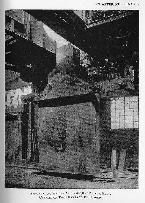
(2) The ingot, while still hot, is stripped from the mould, cleaned, and prepared for forging (Plate I).
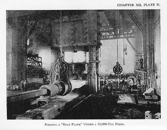
(3) The ingot is then reheated and forged under a hydraulic press to within about 15 per cent of the final thickness. The forging reduces the ingot to about one-third of its previous thickness. The segregation of impurities in the central upper portion is discarded by cutting off (Plate II).
(4) The forging is annealed to produce a partially fibrous condition of the microstructure to prevent cracking in cooling and to eliminate the strains due to forging.
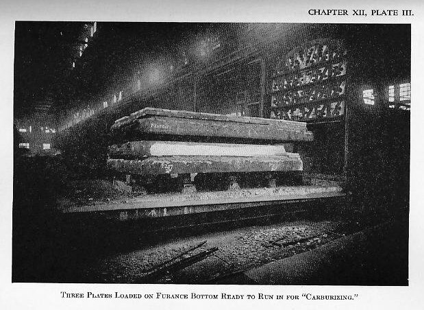
(5) It is then super-carburized (Plate III). The time required for this step varies with the size of the forging; large forgings take from 10 to 14 days.
(6) Reheating, reforging nearly to the final thickness, and annealing follow.
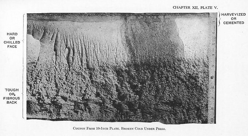
(7) Several heat treatments may follow to develop the proper physical properties in the fiber (Plate V).
(8) The forging is next machined to the rough dimensions.
(9) It is then reheated and formed to shape.
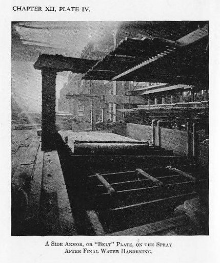
(10) The front face is then heated above the critical temperature, depending upon the depth of chill desired, and hardened by oil or water spraying (Plate IV).
(11) After low heating, the curvature of the plate is rectified.
(12) The plate is machined to the finished dimensions.
1209. Non-cemented armor
From the discussion of decremental hardening as applied to K. C. armor, it is quite apparent that a plate may be hardened without prior cementation. It should be mentioned here that the carburized face is much more liable to tearing and cracking during forging and bending to shape than is the other portion of the plate, a condition which renders the fabrication of thin plates more difficult than thick ones. These facts led the Bethlehem Steel Company to undertake the manufacture of armor by the general Krupp process without cementation. Later the Midvale Steel Company adopted the same idea. Such armor is generally referred to as Krupp non-cemented or K. N. C. armor. In structure this armor differs appreciably from K. C. armor. For instance, there is no super-carburized face, and the chill itself is generally harder and somewhat deeper; and there is a further difference in chemical composition, in that, while the carbon and chrome may be somewhat higher, the nickel may be equal or lower, as compared to K. C. armor. Non-cemented armor is fully equal, ballistically, to K. C. armor, and can, in fact, be made of superior ballistic resistance, but it has an unfortunate tendency to spalling, both on projectile impact and from internal strain. It was this tendency to spalling which led to the abandonment of the process after a few years of use. A typical analysis shows carbon as high as .50 per cent, with nickel at 3.5 per cent and chromium at 2.30 per cent to 2.50 per cent.
1210. Summary of armor development
It will be seen from the preceding review that each change in armor has added something, and that modern armor contains all the essentials of each successive product. First, for marine use, we had the simple wrought-iron armor, which was later developed into compound iron-steel armor. Then all-steel armor displaced the compound armor, and was, in turn, improved by the addition of nickel. Next we have a return to the hard face principle, but with homogeneous structure, in the application of Harveyizing. Finally we have the introduction of chromium and the development of decremental hardening as applied to both cemented and non-cemented plates.
The manufacture of efficient armor requires not only a high quality of metallurgical skill, but also expensive tools and equipment. The various improvements in its quality and manufacture have, therefore, been as closely related to the inventions and discoveries of metallurgy as to the commercial growth of the general steel industry. A knowledge of the nature and dates of the various stages in its development, therefore, gives the ordnance student an excellent picture of the evolution of the use of iron and steel. Frequently the demands of the ordnance engineer have caused developments in metallurgy which have had far reaching commercial application, but more frequently the general improvements made by the metallurgical engineer and chemist have opened new vistas to the designers of ordnance.
Class A Armor
1211. Class A armor
The general term Class A armor is applied, in the American Navy, to all face-hardened armor, whether Krupp cemented or Krupp non-cemented.
1212. Ballistic test
During manufacture the processes are watched to insure uniformity in procedure and product. Chemical analyses are made to insure homogeneity in the metal, and test specimens are taken out of the ends of the plates to determine the uniformity of the physical properties. Finally, after water hardening, fragments called coupons are broken off diagonally opposite corners, in order that a microscopical examination may be made of the internal structure. (See Plate V.) Plates are arranged in “groups,” each containing from 600 to 1,200 tons, and after water hardening a plate is selected from the group, sent to the Proving Ground, and there tested ballistically. If successful, the group is passed to completion; if unsuccessful, the group is rejected for retreatment. The ballistic test consists, at present, in subjecting the plate to the normal impact of two major caliber A. P. projectiles at specified velocities, the velocity depending on the gauge of the plate and size of the projectile. This relation will be discussed under the heading of “penetration.”
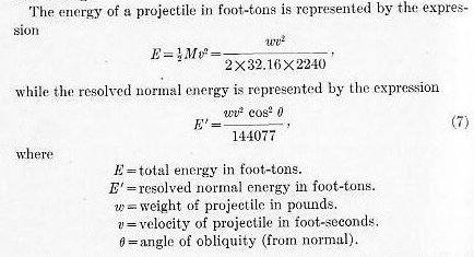
In testing and experimenting with armor, great energies must be absorbed. For instance, a 16-inch projectile striking normally at 2,000 f. s. delivers about 60,000 foot-tons. Assuming that the plate is 10 ft. × 20 ft. × 15 in., that gives about 300 foot-tons per square foot of plate area, or about 1,100 foot-tons per ton of plate. The structure to which the plate is attached must, therefore, be of great strength. Such structures are called plate-butts. Similar structures used for testing the action of projectiles against plates are called projectile-butts.
Particular attention must be given in conducting all impact tests to eliminate, so far as is possible, all movement of the attacked plate, or, in other words, to preserve the rigidity of the structure as a whole. This is particularly true when plates are attacked at other angles than normal, for in such cases there may be most powerful end thrusts, which, if uncontrolled, will permit end movement and therefore subject the projectile to uncontrolled and unknown “whip,” thereby vitiating the value of the test.
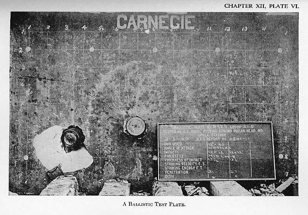
Plate VI shows an armor plate after undergoing test. The two shots required for the routine ballistic test are for the purpose of determining whether the manufacturer’s current manufacturing methods, in general, and the group represented, in particular, are up to the required standard. That condition having been established, and the group’s acceptability settled, it is customary to attack the plate with one or two additional shots to determine its precise ballistic limit. To determine this ballistic limit the velocity of impact is increased until penetration is just or nearly secured. Experienced personnel can, with ordinary armor, generally secure this result (after two ballistic test shots) in two more shots, and sometimes even with one shot.
In experimenting with and testing armor it is the ballistic limit which is the significant figure. How it is expressed will be shown later. But it is readily seen that by always working for it, a record can easily be compiled, in time, which will show not only the general average of performance, but also the peak of performance. And by always carefully investigating the plates which give the greatest resistance, the general standards may be raised.
1213. Penetration
Considerable discussion took place in early days of ship armor as to whether armor could best be defeated by “racking” or “punching.” Racking was produced by very large solid ball shot at low velocity and resulted in knocking plates off the ship’s side, thus exposing her vitals; and punching was produced by elongated projectiles, at high velocity, and resulted in perforation and the immediate attack of the ship’s vitals. This discussion was settled during our Civil War very emphatically, and later in the Huascar-Cochrane and Blanco Encalado engagement; for the shots which secured decisive effects, practically without exception, were piercing shots. This discussion finds its echo in more recent controversies concerning the relative merits of armor-piercing and high-capacity projectiles. Here, again, war decided emphatically, for in the World War it was conclusively shown that the decisive hits were those made by armor-piercing projectiles.
The principal function of armor is, therefore, to prevent, so far as possible, the penetration of a projectile into a ship. But the “racking” effect cannot be neglected. This is at present, primarily a matter of securing; but the use of guns with projectiles of great weight, the demand for increased speed and consequent sacrifice in protection, and the probable obliquity of impact, are gradually forcing attention back to the “racking” or “smashing” attack.
The penetration of a pointed projectile into a homogeneous or simple plate was very accurately expressed, in the early days of armor, by various empirical formulas. The one which has survived the various developments, and is still the basis of armor calculation, is that of a Frenchman, J. DeMarre.
This formula, as used in the late eighties and as applied to the penetration of cylindrical projectiles with ogival heads into plain wrought iron, is as follows:
Problem I.—How far will a 10-inch 500-pound projectile penetrate a wrought-iron plate at a striking velocity of 1,772 f. s.?
Answer: 23.1 inches.
1214. Penetration of nickel-steel armor
Subsequent to the adoption of nickel-steel armor, the formula was revised and, when applying to that material, is used in the following form:
Problem II.—How far will a 10-inch 500-pound projectile penetrate into a nickel-steel plate at a striking velocity of 1,772 f. s.?
Answer: 15.77 inches.
Problem III.—What is the ratio between penetration in wrought and nickel-steel?
In nickel-steel armor, the projectile encounters a homogeneous material and therefore a more or less constant resistance. In face-hardened armor the projectile encounters media of varying hardness and strength, and its retardation follows laws which can be but imperfectly stated. For purposes of comparison, therefore, the limit of resistance of face-hardened plates is generally referred to a basis of penetration of nickel-steel.
1215. Penetration of face-hardened armor
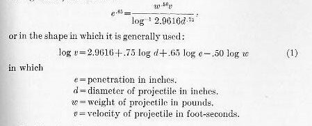
The factor of performance.—Upon the introduction of face-hardened armor, therefore, the DeMarre formula was modified by introducing a coefficient of reduction (K), thus:
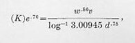
or in the form in which it is used:
Problem IV.—Assuming K as 1.23 for a particular Class A plate, what would be the penetration of a 6-inch A. P. projectile weighing 105 pounds at 1,836 f. s. striking velocity?
Answer: 7 inches.
The most useful and frequent application of the formula in this connection is, however, to determine the comparative value of plates. If we determine by test the velocity at which a plate just resists penetration or just permits penetration by a particular projectile, we may consider the coefficient of reduction, mentioned above, as a factor of performance, and then solve the equation to determine the factor of performance. The formula then becomes:
This formula is very useful for normal impacts, but, like all empirical formulas, it has its limitations. It is most accurate and useful at striking velocities between 1,400 f. s. and 2,000 f. s. and when the ratio between the diameter of the projectile and thickness of plate lies between 1.2 and 0.7; but it is liable to give erratic or misleading results when those limits are exceeded. The formula (in addition) assumes similarity of projectile quality and penetrative ability.
Problem V.—Find the maximum factor of performance, or, as it is generally expressed, the DeMarre coefficient, of a particular K. C., 12-inch plate.
Solution: Let us assume that our recent experience in testing armor has shown that the average DeMarre coefficient is about 1.16. Experience has also dictated that the DeMarre coefficient of a plate can be most reliably and usefully determined when even caliber projectiles are used. (By even caliber, we mean that the caliber of the attacking gun and thickness of the plate are the same.) We therefore decide to use the 12-inch gun, with an 870-pound projectile, with which to secure our data.
By solving formula (3) for the assumed conditions, we get 1,463 f. s. We fire a shot at this velocity and learn that the projectile penetrated by a small margin, the amount of margin being approximated by its travel after penetration.
We fire a second shot at a velocity of 1,400 f. s. and the projectile fails to penetrate, but it is evident that a slightly greater velocity would have caused penetration. We conclude that a velocity of 1,420 f. s. would have just caused penetration. With this figure we solve formula (4) and determine:
The maximum factor of performance of this plate is 1.12, or, in other words, its limit of resistance is represented by a DeMarre coefficient of 1.1165.
Problem VI.—A 14-inch Class A plate was attacked as follows:
First shot, 12-inch 870-pound projectile, at 1,500 f. s. Penetration, 10 inches.
Second shot, similar projectile at 1,545 f. s. Penetration, 13 inches.
Third shot, similar projectile at 1,590 f. s. Penetration complete.
What DeMarre coefficient expresses the limit of resistance of plate?
Answer: About 1.108 at v = 1,570 f. s.
Problem VII.—A 13-inch Harveyized nickel-steel plate was just defeated by a 10-inch 500-pound projectile, at a velocity of 1,620 f. s., while a 12-inch K. C. plate was just defeated by a similar projectile at a velocity of 1,685 f. s. What is the relative value of the two plates?
Answer: Harvey plate is to Krupp plate as 1 is to 1.216.
1216. Oblique attack
It will be accepted, without proof, that by inclining a plate to the line of fire its resisting power is enhanced. We may state this in two ways: first, as the angle of obliquity increases, with a given plate, the projectile will require a greater velocity to penetrate; or, as the angle of obliquity increases, there is a decrease in thickness of the plate necessary to defeat a given projectile at a constant velocity.
The angle of obliquity is the angle between the normal to the face of the plate and the axis of the projectile at the point of impact.
Considerable experimentation has shown that while the ratio is obscure throughout the entire quadrant (angle of obliquity 0° to 90°), a much clearer relation is shown in each of the three sectors: angle of obliquity 0° to 30°, from 30° to 60°, and from 60° to 90°. That is to say, having determined the velocity necessary to defeat a plate at, say 45°, the velocity to defeat the plate at angles of obliquity between 30° and 60° may be fairly accurately determined by applying a given ratio to velocity which caused defeat at 45°. Or, having determined the defeating velocity of a plate with given projectile at 15°, one may predict with reasonable accuracy, the defeating velocity with that projectile and plate at angles of obliquity between 0° and 30°.
It should be borne in mind that there is a real difference in the action of the plate and projectile in the three sectors mentioned above, the change from sector to sector being gradual. However, in the most oblique sector, that from 60° to 90°, there is a decided difference from other two, for in this sector we are dealing with the glancing blow in most pronounced form. This difference has given rise to a specific class of armor, designed to care for this particular condition.
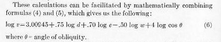
Experiments have indicated that the velocity necessary to defeat a plate varies about as the fourth power of the secant of the angle of obliquity.
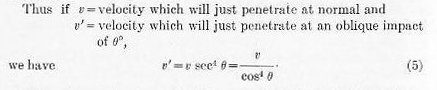
This ratio can be reduced to figures, and when so used is generally referred to as an “angle multiplier.” In order to plan an attack on a given plate we fix the normal velocity by the DeMarre formula (4) and apply the “angle multiplier” as determined by the above formula (5) to fix the velocity for the specified test.
In the sector from 0° to 30°, the ratio is more or less correct, while in the middle sector, from 30° to 60°, it can be used as a basis of comparison.
Or, if we know with reasonable certainty the velocity necessary to effect penetration at a given angle on a particular plate and desire to calculate the velocity required to penetrate a plate of different thickness and equal ballistic resistance, we would divide the velocity by the angle multiplier, then use the DeMarre formula (5) to calculate the relative velocities on the basis of normal impact, and finally secure our desired result by applying the “angle multiplier” to our calculated normal velocity.
In our discussions of Class A armor penetration and the use of the DeMarre formula, we have thus touched on two special factors: the factor of performance for normal impact, and the angle multiplier for oblique impact. In experimental work it is well to keep these two factors separate and distinct, and to plan and work out our problems so that the ratios between different plates are kept related to these two separate factors.
Class B Armor
1217.
Prior to the introduction of compound or face-hardened armor all armor aboard ship was the same. It early became apparent that face-hardened armor was less effective against glancing impacts of considerable obliquity than was an equal weight of homogeneous armor. The advent of K. C. armor further strengthened this conviction. The development of a special armor to resist glancing blows dates, therefore, from the introduction of face-hardened armor. It is apparent, in the glancing blow, that a hard face is unnecessary, and that what is desired is a combination of the highest strength and ductility, in order that the projectile may be gradually deflected. In other words, against this attack, we permit the armor to give under the blow, thereby spreading the effect, while the projectile slides along the trough it creates, thus further spreading the effect, and finally is completely deflected. In a normal impact the blow is largely limited to a circular area with a diameter of about three calibers (see Plate VI), while in a glancing impact, for instance 15°, the effect of the blow is taken on an area about three calibers wide and about four to five calibers long.
Armor to resist the glancing blow is now called “Class B Armor” in the U. S. Navy, but it is also referred to as deck armor, horizontal armor, and special-treatment steel.
Nickel-steel continued to be used for horizontal armor until about 1909 when several developments took place. About that time the Carnegie Steel Company applied the newly developed nickel-chrome-vanadium alloy-steel to this armor and the change in composition and increased metallurgical skill enabled its resisting powers to be considerably increased. In that year the ballistic test of horizontal armor, for protective decks, turret tops, etc., began. About 1914 the use of vanadium was discontinued. At present, a nickel-chrome steel of approximately the same chemical composition as Class A armor is used, that is, carbon about .30 per cent, nickel about 3.85 per cent, and chrome about 1.85 per cent.
Class B armor, when less than 4 inches thick, is rolled in a mill instead of being forged, but above that thickness it is forged, as rolling thick plates is believed to work the plate less uniformly than forging, a condition which would, of course, tend to reduce ballistic resistance. Above 4 inches, if the plates are large, forging must be resorted to as there are no American rolling mills equipped to handle the required ingots. The treatment is quite different from that of K. C. armor, for the desideratum is to secure great strength and ductility. Thus tensile test specimens frequently show an “ultimate strength” as high as 115,000 pounds per square inch with an “elongation” in two inches of 23 per cent and “reduction in area” of 65 per cent.
1218. Ballistic test
Class B armor is handled in “groups,” as is A armor, and each ballistic plate is subjected to the impact of a major-caliber projectile at angles of obliquity, depending on the thickness of the plate, from 80° up to about 55°.
Comparisons between plates and calculations as to the suitability of plates between about 4 inches and 9 inches to meet certain conditions may be approximated by the following mathematical methods. These are not applicable to plates less than 4 inches thick.
In the first place the resolved normal energy is used to represent the force acting.
As a rule the angle of attack, or the complement of the angle of obliquity, is taken in degrees as about four times the plate thickness in inches and the caliber of the projectile is taken as about two and a half times the plate thickness for 4-inch plates and twice the plate thickness for heavier plates.
Using this formula, striking velocities may be calculated upon which to base a test with a reasonable certainty that the limit of the plate may be approximately reached.
Problem VIII.—Determine the condition under which the first shot shall be fired to determine the limit of a 5.5-inch Class B plate.
Answer: Select a 14-inch gun (projectile weighing 1,400 pounds). Select 68° as the angle of obliquity. Then v = 1,860.3 f. s.
The above mathematical process is by no means thoroughly reliable, but it may be useful in handling comparative tests.
1219. Armor bolts and securing
References made heretofore in regard to armor butts, testing, and inclined armor, and a consideration of the enormous forces concerned on impact, point out the necessity of properly securing armor to the structure of the ship. Experiment only increases the importance to be attached to the subject. Many experiments have conclusively shown that all flexible mountings, such as steel springs, rubber buffers, etc., designed to absorb energy, cushion the plate, or extend the time interval in which the plate can act, are not only of no value, but are, on the contrary, a source of actual weakness.
Class A armor is bolted to the skin of the ship, or to her framing and bulkheads, with heavy bolts of special design called “armor bolts.” As it is impossible to fit the armor plate snug against the shell plate, this support is provided by standing the armor off from the plating, leaving a space about 2 inches wide between the plating and the armor. This space is then filled with concrete which provides an equally distributed support to the armor over its full surface. (See Fig. 1201.) In addition to bolting, abutting edges are keyed together with a double tongue-and-groove key which is driven in endwise; and plates which meet at angles are rabbeted. (See Figs. 1202 and 1203.)
Class A armor is seldom considered as a factor in the strength of the ship’s structure.
Class B or deck armor, however, is generally worked into the structure. Deck armor, except with the heaviest plates, is riveted as in ordinary plating. The heaviest plates in decks and the tops of turrets and conning towers are secured with bolts in a similar manner to class A plates except no backing is used.
Armor bolts are spaced to provide one bolt for every five square feet of surface, so far as the framing behind the armor will permit, except in the case of 3-inch armor, for which one bolt is used for about six square feet of surface.
Armor bolts are made from good quality nickel steel (about 3.5 per cent nickel), for the bolt must be strong enough to hold the plate and be ductile to permit the plate to warp and spring under projectile impact without cracking.
Light Armor and Distribution of Armor
1220. Light armor
During the World War, insistent demand resulted in the development of a third type of armor, generally called light armor. On armored ships light armor is used to protect personnel and instruments against machine-gun fire from aircraft. Against machine-gun and small-arms fire, light armor is also used to afford protection to, for instance, machine guns, light artillery, boats, vital parts of the body, and its use may be extended to the protection of personnel and vital parts of aircraft.
In some of these uses, as for instance body armor and aircraft armor, the greatest possible protection must be secured with the least weight, a condition imposed on all armor, in fact, but most accentuated in these uses. In this type of armor the metallurgist can use his utmost skill, for the mass is small. One might almost say that laboratory methods may be followed. This branch of the art is too young to permit of classification. So far no attempt has been made to face harden, for the thickness varies between 1/16 of an inch for body armor up to about an inch.
Generally speaking, this armor resembles Class B armor, although many special and expensive alloy steels are being tried. We find the so-called, high-silicon, high-manganese, vanadium, zirconium, cobalt, chrome, and nickel alloys in various proportions and combinations, and plates have been tested giving, with fair ductility, ultimate strengths per square inch as high as 250,000 pounds. One fact seems to stand out—as desirable as is strength—good ductility is a necessity.
1221. Arrangement and distribution of armor
Armor serves two purposes: (1) protection for the water-tight integrity and interior mechanism of the vessel, and (2) protection of the personnel.
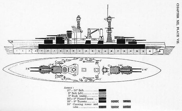
This protection is afforded to as great an extent as possible by the armor belt, extending the length of the vital parts of the ship, the casemate armor, the protective deck, turrets, barbettes, gun shields, and conning tower.
The arrangement and distribution of armor on ships of various classes is described in works on naval construction, to which the reader is referred for details. Plate VII illustrates the distribution of armor on the West Virginia class of battleships.